Speed 400
Cloudster Project
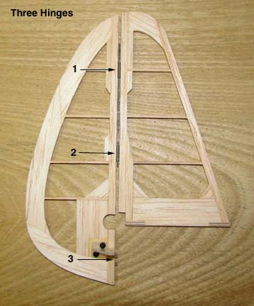
First order of business was
to hinge the rudder as shown below. As you can see, three of the small Du-Bro
nylon hinges were used, two up on the fin, and one down on the bottom of the
rudder to attach to the fuselage's tail post. Back up pieces were glued to
the inside of the spars where the hinge halves go through to reinforce the
slot and isolate the interior of the surfaces from the hinge slot openings.
Notice that the cut out for the elevator spar carry through is not large
enough yet, but it will be finalized after the elevator is hinged. Notice
the rudder's control horn is also installed.
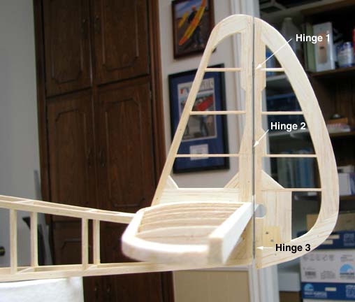
This picture shows the
rudder/stab mounted to the stab platform on the fuselage. The bottom of the
rudder was intentionally left wide so it could be trimmed off to match the
bottom of the fuselage.
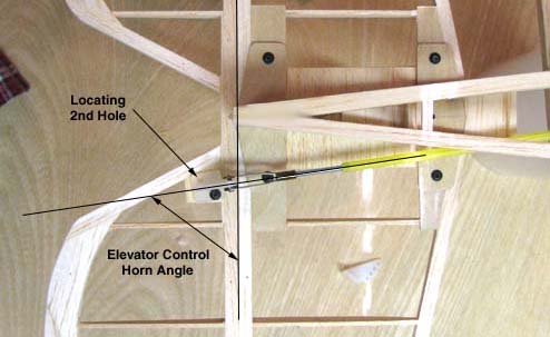
If you remember in Report No. 16, only one 2-56 hole
was drilled and tapped in the spruce base for the elevator control horn. In
the picture below, the elevator has been taped to the stab and a temporary
push rod/clevis connected to the control horn. Then the push rod was
oriented to the angle it will exit the side of the fuselage. As you can see,
this allows the control horn to be turned to the proper angle to line up
with the push rod, which in turn locates the desired position of the second
hole in the control horn base.
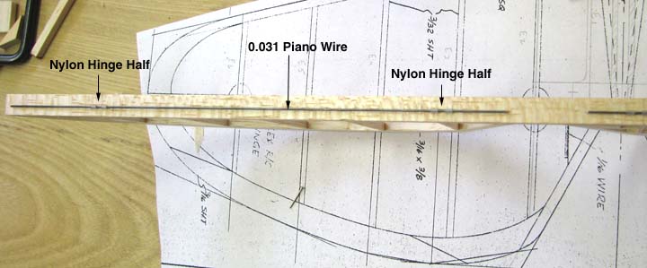
The picture below is an edge view of the elevator's
main spar. This shows you the two hinge halves installed with the a
continuous wire pin running through the hinge loops. With a continuous wire
pin, these small hinges allowed me to keep the gap down to less than 1/16".
The 1/32" piano wire that I have measures 0.032" and it is slightly too
tight to go through these hinge loops without a lot forcing. However, I
found some 10" lengths of 0.031" piano wire that I got somewhere a long time
ago that slips through these small hinge loops with ease.
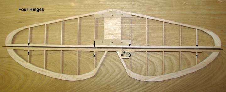
This picture shows a bottom view of the hinged
elevator to the stab. There are four hinges, two on a side as the plans call
for. Two separate continuous wire pins are used for the right and left sides
of the elevator to eliminate having to push one continuous hinge pin through
four hinges down entire length of the stab. Again, back up pieces have been
glued to the spars where the hinge halves go through to reinforce the slot
and isolate the interior of the surfaces from the hinge slot openings. If
you look close, you can see the elevator's control horn's second mounting
hole has been drilled and tapped with the 2-56 cap screw now in place.
This afternoon, I will start carving and shaping the
vertical and horizontal tail surfaces to form the rounded leading edges and
tapered trailing edges, which will finish up the entire tail structure ready
for covering.......................Tandy