Speed 400
Cloudster Project
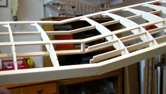
After the right wing's glued and clamped inner and tip panel joint had dried
overnight, the right wing was removed from the plan. Then with great care,
the two temporary polyhedral ribs that had been clamped together were
carefully cut into sections and removed as shown below. Notice that the
portion of the two temporary polyhedral ribs between the upper and lower
3/32" X 1/4" main spars was left in place. This preserves the vertical
spacing between the upper and lower spars.
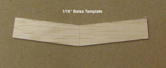
In
order to fabricate a plywood polyhedral brace that will fit between the two
main spars, a template was drawn by pressing a trimmed sheet of 1/16" up
against the forward face of the main spars and tracing an outline from the
rear inside the two spars. The 1/16" balsa template was cut out as shown
below.
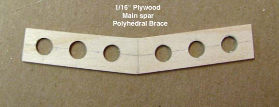
The
balsa template was then placed on a sheet of 1/16" plywood and the pattern
traced onto the plywood. The plywood brace was cut out and sanded to fit in
between the two main spars (things like this never fit properly without a
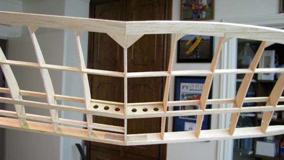
little hand tweaking). As part of the Cloudster's on going weight saving
effort, six 1/4" lightening holes were carefully located and made in the
plywood brace as shown below before it was glued in between the two main
spars.
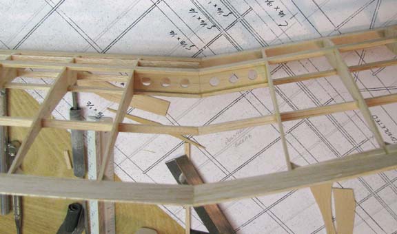
The
finished plywood brace was slipped into place between the two main spars.
The 1/4" wide spars are much wider than the 1/16" brace. Since the main
spars are 1/4" wide, the brace will be centered inside the spars when there
is a 3/32" distance between the edges of the spars and the brace (i.e., 3/32
+ 1/16 + 3/32 = 1/4). Therefore a piece of 3/32" balsa was used to center
the brace before it was permanently glued in place as shown below.
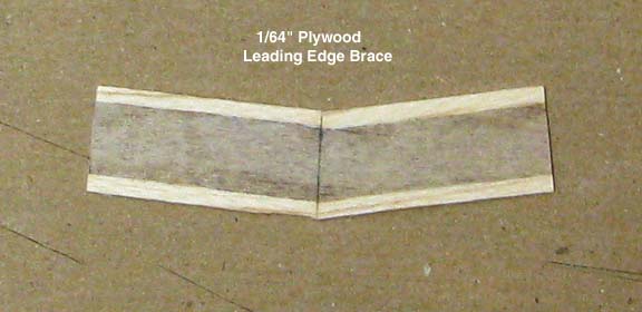
Even
though there is a large cross sectional gluing area on the 1/4" X 1/2"
leading edge, a leading edge brace was made out of 1/64" plywood to add
further support. The brace's edges were lined with balsa as shown below so
they would sand smoothly when the balsa leading edge is carved and sanded to
shape.
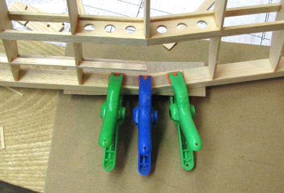
The
leading edge brace was glued with aliphatic glue and clamped to the inside
face of the leading edge as shown below.
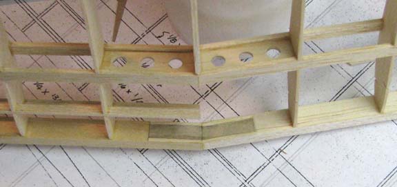
Once
dry, the clamps were removed, which is shown below. This brace adds
considerable strength to the leading joint at the cost of very little
weight.
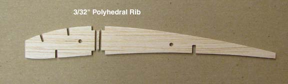
Using the R1 plywood template made in Report No.29, a polyhedral rib was
made from 3/32" sheet balsa. The polyhedral rib was made thicker for
attaching the wing covering to. This rib was had a 1/16" strip cut from the
center for the polyhedral brace as shown below.
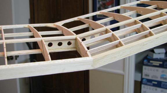
The
two segments of the polyhedral rib was glued into place and the trailing
edge polyhedral joint was reinforced with two large 1/16" gussets (0.6" on a
side) as shown below.
This
shows the polyhedral rib glued in place from the top side.
Next
the three 1/16"" X 3/16" turbulator spars will be added to the wing's tip
panel and the wing tip will be trimmed and sanded to final shape.
HAPPY NEW YEAR
..........Tandy..........