Speed 400
Cloudster Project
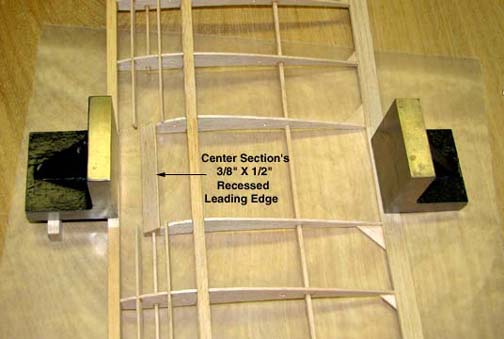
The first step in creating the
wing's recessed leading edge is to make the center section's portion of the
leading edge out of 3/8" X 1/2" balsa stock. The forward portion of
the 1/2" height is beveled down so that the front face is only 1/4"
high. Next the forward portion of the two R1 center section ribs are trimmed
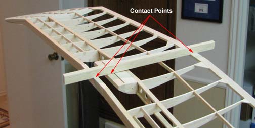
down and then the leading edge is glued in place as shown below. To make
sure the bottom face of the leading edge lies in the same plane as the
center section's temporary leading and trailing edges, the wing center
section's temporary leading and permanent trailing edges were firmly
weighted down to the work table with two square steel blocks as shown
below.
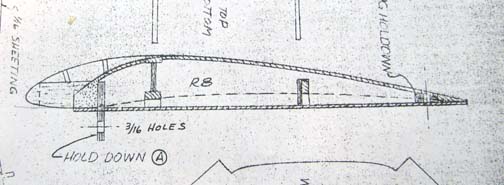
This excerpt from the Jim Adams
Cloudster plan details the wing center section showing the forward plywood
plate that extends down below the bottom of the center section for the
forward wing attachment to the fuselage.
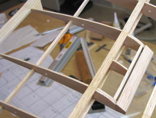
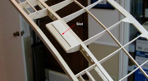
The picture below shows the
center section structure that was added forward of the main spar. It consist
of three 1/16" balsa sub ribs and a 3/32" balsa back plate with a beveled
top behind the leading edge to form the slot for the 1/16" plywood plate.
Notice the rather sharp curvature of the ribs between the leading edge and
the main spar.
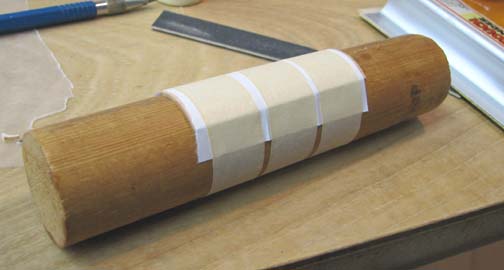
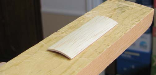
To accommodate this curvature, a
piece of 1/16" balsa sheet was wetted and taped around a 1-3/8" wooden dowel
to pre-form the curvature as shown below.
Once dry, the tape was removed
and the resulting preformed 1/16" sheet is shown in the picture below.
The pre-forming step makes it
much easier then to glue the 1/16" balsa sheeting to the top of the forward
center section structure as shown below.
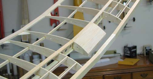
Slightly curved 1/16" balsa sheeting was also glued to the bottom of the
center section between the main spar and the 3/32" balsa back plate,
leaving the 1/16" wide slot open.
The temporary leading edge and
permanent trailing edge have served well as a jig to accurately position the
center section's permanent leading edge. In the picture below, you can see
that all three lie along a straight line.
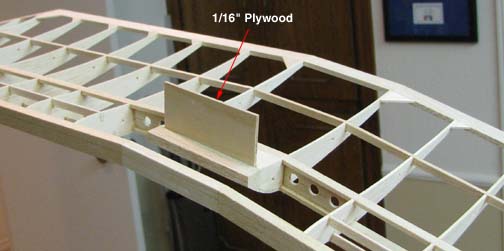
In the picture below, a piece of
1/16" plywood has been slipped into the slot for a test fit. After the wing
is finished and covered, the finished wing attachment plywood plate will be
glued in place.
Tomorrow the two curved portions
of the recessed leading edge will be cut out and glued in place. Then the
temporary leading can be removed leaving the sculptured recessed leading
edge....................Tandy