Speed 400 Cloudster
Project
It was intended that the battery box made in
Report No. 56 was to be glued into the fuselage structure. However, this
will require a hatch in the bottom of the fuselage to get the Li-Po battery
out for charging. As you well know, constructing and installing a hatch is
a significant undertaking and should be avoided if at all possible. To
address this issue, a design to make the battery box removable was developed
so that the battery in its box can be installed and removed through the top
opening in the fuselage under the wing.
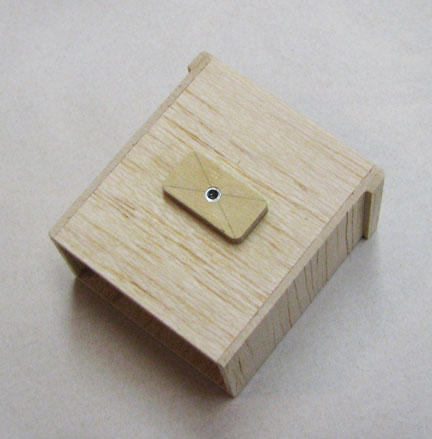
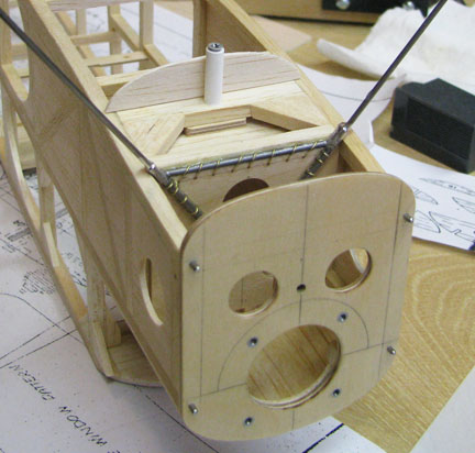
The first task was to provide an attachment hard
point on the battery box itself. A small rectangle was cut out of 1/8"
plywood. A hole was drilled in the center and a 2-56 blind nut was embedded
in the plywood. Another hole was cut out in the center of the bottom of the
battery box for the head of the 2-56 blind nut to fit down into so that the
plywood rectangle would fit down flush on the bottom of the battery box when
it was glued in place as shown below. Notice the slightly rounded forward
edges on the forward face of the box to assist in aligning the box up
against the firewall.
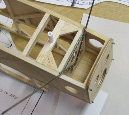
The second task was to provide adequately strong
attachment structure in the bottom of the fuselage to secure the battery box
to. A hole was drilled in the center of a wide cross member and a length of
ABS tubing was CA'd in the hole. This cross member was indexed in the
fuselage structure with the battery box in its desired location and then the
cross member was glued in place as shown below. Notice the two triangular
gussets securely tying the cross member to the bottom longerons for
additional strength.
This picture shows the battery box attached to
the fuselage with a long 2-56 screw inside the ABS tube.
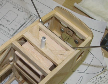
The ABS tube was intentionally left long so that
after the fuselage's bottom bulkheads and stringers are in place, the screw
can be inserted from outside the fuselage as shown below. The tube will be
trimmed and sanded flush with the bottom of the finished fuselage structure.
Some battery/battery box trial installations and removals in the presents of
all of the ESC wiring will have to conducted to make sure of the
functionality of this design before the requirement for a hatch is
abandoned. The functionality has to include both the installation and
removal as well as connecting the battery to the ESC.
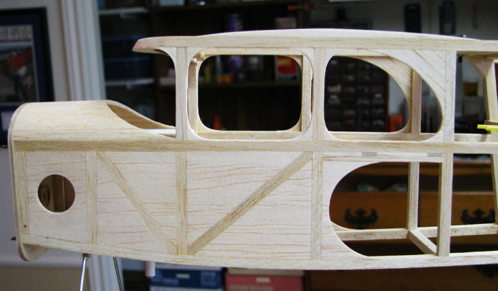
Additional work was also done to complete the
window openings by adding 3/32" fillets in the corners and sanding them to
shape as shown on the right side of the fuselage below.
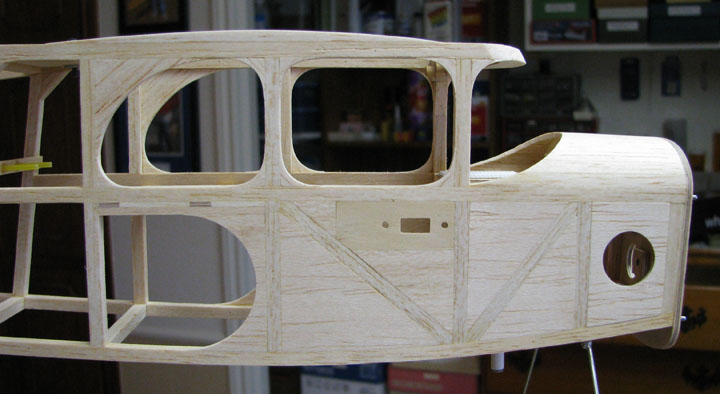
This picture shows the window openings on the
left side of the fuselage. The sides of the fueslage have yet to be sanded
to produce a smooth and integrated inlay surface, which is the "proof of the
pudding" as they say...............................Tandy