Speed 400 Cloudster Project
Most of the afternoon today was spent wiring up
the Electronic Speed Control (ESC) to Speed 400 motor using the polarized
connectors recommended by Jay Burkart. The close proximity of the motor to
the ESC dictated a close tolerance hook up with very little wire involved.
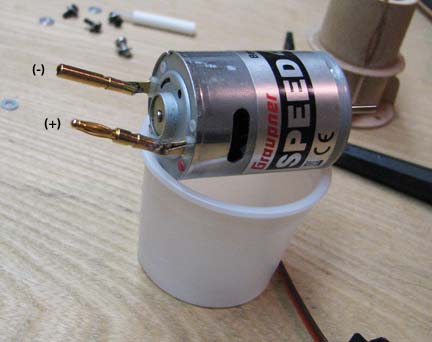
As per Jay's recommendation, the male connector was soldered directly to the
(+) motor terminal and the female connector was soldered directly to the (-)
motor terminal as shown below. Notice that the connectors are angled up
about 35 degrees to the axis of the motor in order to line up with the
connectors coming from the ESC.
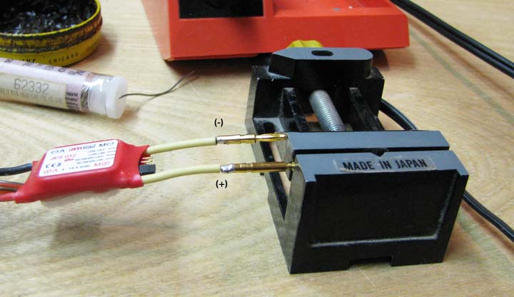
This picture shows how short the ESC wires had to
be cut. The male and female connectors are soldered to the ends of the wire
as shown below.
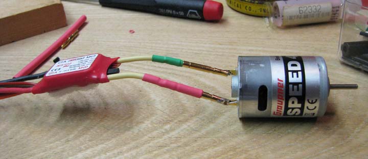
Red heat shrink tubing completely covers the ESC
(+) female connector to prevent it from coming in contact with the male (-)
connector when they are not connected to the motor as shown below. Notice
how little wire is used.
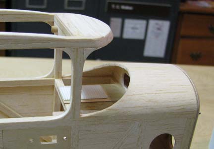
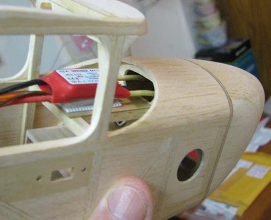
For installation, the ESC is first connected to
the motor. Then the ESC is inserted through the hole in the firewall from
the front and back through the hole in the bulkhead under the turtle deck
planking. Once through, the ESC is secured to the Velcro pad shown below. Of
course it is virtually impossible to get the ESC in the proper position on
the Velcro pad because it keeps sticking to the Velcro pad as soon as it
touches it.
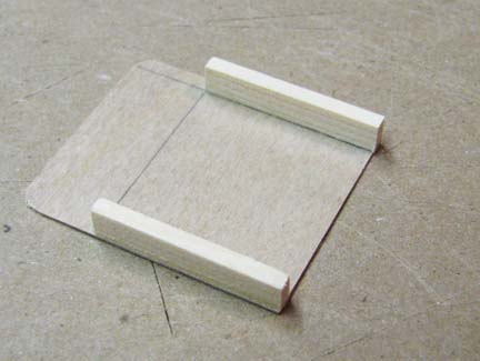
Therefore, to solve this problem, a Velcro
separator cover was made as shown below. The cover consist of a 1/64"
plywood plate with two 1/8" X 3/16" spruce runners glued to the edges as
shown below.
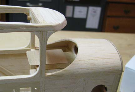
The Velcro cover is dropped into place over the
Velcro pad and is held there by the two runners on each side as shown
below.
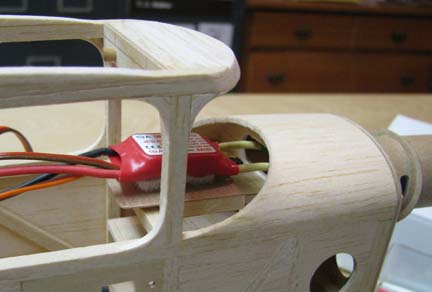
In the picture below, the ESC has been connected
to the motor, inserted through the hole in the firewall from the front, and
back through the hole in the bulkhead under the turtle deck planking. Notice
that the fussy side of the Velcro on the ESC is kept separate from the hook
side on the pad by the Velcro cover and can be placed in proper position.
Once the ESC is in proper position, the ESC is
simply raised up and Velcro cover is slipped out, allowing the Velcro fussy
side to mate with hook side as shown below.
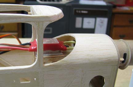
With a slight downward pressure on the ESC, it is
firmly secured to the Velcro pad as shown below.
So now we have the motor and ESC wiring and
installation worked out. Tomorrow will be spent wiring up the LI-Po battery
to the ESC using the polarized connectors and determining if the battery can
be installed and connected to the ESC from the cabin opening under the wing
without having to have a hatch opening in the bottom of the
fuselage......................Tandy