.JPG)
Goldberg "Gas Bird" Construction Project Session #1
By Tommy Gray
AMA 17063
The Goldberg "Gas Bird" is a great little airplane. I am building mine from a "Klarich" kit given to me by friend Glen Poole. I am wanting to use it for a couple of classes at the upcoming SAM Champs this year (2009). There are two different variations of the little plane. Both are pylon planes with the same wing area and span. The original one published in 1938 is called the "Gas Bird".
The latter one published in 1939, is called the "Diamond
Zipper". It has a little of the later "Zipper" appearance, but has the diamond
shaped fuselage of the original Gas Bird, and not the rounded fuselage of the
Zipper. The "Diamond Zipper" also has a stab that is curved at the back.
The "Gas Bird" stab is straight across the back and straight tapered from the
front. I want to build the "Gas Bird", as it is a true "Antique" class
plane, having been published in 1938. The picture above is not that great, and I
have not found another so it will have to do for now.
I plan to power the Gas Bird for the Ohlsson .23 event, with a nice little .23 Sideport
Ohlsson ignition engine I picked up last year. As you can see in the next
picture it is a very nice and a clean little engine. The Sideport is in
the first picture, and has the fuel tank and venturi at the rear of the crankcase, as
opposed to the front rotor .23 I have shown in the second picture for comparison.
The Sideport gets its name from the fact that the intake is kind of on the "side"
of the engine (notice the bulge on the side of the engine beneath the exhaust
port) where the intake tube connects to the crankcase. This is different
from the front induction (Front Rotor) model shown in the second picture.
Ohlsson .23 Sideport shown below
.JPG)
Ohlsson .23 Front Rotor Shown Below
.JPG)
The majority of modern engines are front rotor (front intake) style as is the Ohlsson .23 FR above (which by the way, is not an ignition engine but rather a glow engine (notice the missing timer and points at the front).
The Airplane
The specs on the plane are 48" wingspan, and 386 Sq. In. wing area. This will make it suitable for the Ohlsson .23 event, and also make it perfect for class A LER with just an engine change, as the wing area will allow up to a .15 size engine (actually a .17, but have you ever seen a .17 size engine?? I haven't). Hopefully this will work out as I have planned.
Getting Started....
Most folks have a sequence they like to use when building a new plane. I guess I am no different, except that to avoid burning out on the project, I always try to build the part that is the most tedious first. For the "Gas Bird", as with most Free Flight to R/C Conversions I have done, getting elevators into the stab is usually the most work. The free flight planes that our SAM R/C planes are built after had no elevators or rudders, so provision has to be made by modifying the structure to accommodate the modern R/C surfaces. On the last two planes I have built, I have found that if I build the R/C stabilizer in its original form over the plans then modify it after it is built up, I can do the elevators in easy fashion. I will show you what I mean as we go along.
I have already started the structure and since the batteries in my camera died before I could get intermediate pictures, I went ahead and roughed out the stab structure, as you can see below.
.JPG)
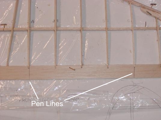
The plans show that the ribs are inset into notches in the trailing edge piece, so I first cut a piece of trailing edge material to length, and then over the plans I marked out the location of all the ribs. I then took the piece out to the bandsaw and cut the notches for the ribs. You can see from the roughed out stab below that the ribs fit nicely.
.JPG)
I had run out of waxed paper so I put some "Saran Wrap" over the plans to keep the piece from being glued to the plans. I usually used waxed paper, but this worked out O.K for now.
To get it this far, I had to cut out the tapered spars according to the plans, and then gently pin them down. I then added the ribs and immediately I was faced with two different problems. First, the last rib on each end was missing (Rib 7A) from the kit. I took some 1/16 balsa scrap and handmade a couple of replacement ribs for the stab. I then tack glued all the ribs in place. I try to avoid pinning anything down as the holes can weaken the structure, so I use a minimum of pins and usually just weight down the sections until the glue dries. In this instance I was tacking with CA so that did not take long. The ribs were slightly long to accommodate the slits in the trailing edge. The second problem however showed up when I put them into the slots. Every single rib was cut wrong. They were too thin in the back and will have to be capped with some pieces of 1/16 square to fill in the gap and to bring them up to the height of the trailing edge piece.
I said there were two problems but in fact there were actually three! When I got everything tacked together and was ready to put in the 3/16" square leading edge, I found that the ribs were too long. The distance from the front spar to the location where the leading edge was supposed to be was almost 1/4" too long and the leading edge stuck out past the plan location. I then had to take a razor knife and carefully trim every rib so that the leading edge could be put in the correct location, to prevent altering the outline shape of the surface which is in violation of the SAM rules (I am a stickler for the rules!!).
Once everything was finally glued in and the surface was roughed out, I was ready to start planning the elevators.
In the picture above, you can see where I am going to cut the stab out for the elevators. I will go into detail on this in the next session. Well, I'm out of time tonight, so I will show you more in a bit!
More to Come......Tommy