Comet Sailplane
Project
Today I finished up clear doping all of
the Sailplane's components as shown in the table below. As you can see,
there is total of 14 coats of clear dope on all 12 components. At 1-1/2
hours per coat, I spent 21 hours just doping the wing! Thank goodness that
is over. :O<
|
Component |
Wood |
Polyspan |
Silk |
Orange Tint |
Yellow Tint |
Orange Tint |
Yellow Tint |
||
|
Mix |
50D/50T |
50D/50T |
50D/50T |
50D/50T |
50D/50T |
40D/60T |
40D/60T |
||
|
Retarder |
None |
None |
None |
None |
None |
1/2 oz |
1/2 oz |
||
|
Stab |
3 |
3 |
3 |
3 |
3 |
2 |
2 |
||
|
Sub Fins |
3 |
3 |
3 |
3 |
None |
2 |
None |
||
|
Elevators |
3 |
3 |
3 |
None |
3 |
N/A |
2 |
||
|
Fin |
3 |
3 |
3 |
3 |
None |
2 |
None |
||
|
Rudder |
3 |
3 |
3 |
3 |
None |
2 |
None |
||
|
Sub Rudder |
3 |
3 |
3 |
3 |
None |
2 |
None |
||
|
Wing |
3 |
3 |
3 |
3 |
3 |
2 |
2 |
||
|
Hatches |
3 |
3 |
3 |
3 |
None |
2 |
None |
||
|
Fuselage |
3 |
3 |
3 |
3 |
None |
2 |
None |
||
|
Cowl |
3 |
3 |
3 |
3 |
None |
2 |
None |
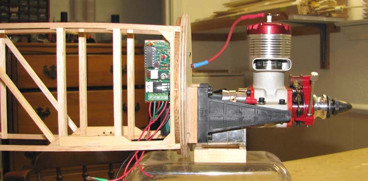
I always use two external pins for the (+)
charging terminal to the ignition battery and the (+) booster terminal.
Grounds for both are provided by the landing gear, which is grounded to the
engine. Our good friend, Marvin Stern has recently incorporated provisions
booster wiring in his outstanding Aero Tech IGN-SW ignition unit shown
below. This permits starting the engine without the use of the radio.
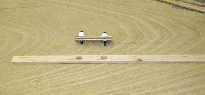
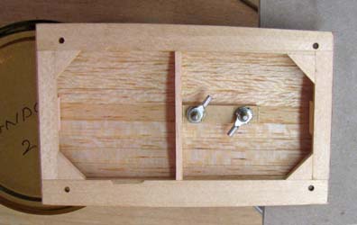
The forward hatch cover behind the firewall was
designed to support both the (+) booster external pin and the (+) ignition
battery charge external pin. From Report No. 35, the hard points for these
two pins were integrated into the cover's planking. Shown below are the hard
point assembly consisting of two 2-56 blind nuts embedded into a piece of
1/8" plywood with ABS plastic stand offs. A strip of the 3/32" X 1/4" strip
planking with two holes to receive the stand offs is also shown.
The two hard points were incorporated into the
planking of the forward ignition hatch cover as shown below.

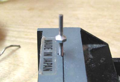
Now I want to share with you my technique for
making external pins. I use a standard push rod with 2-56 thread son the
end. A 2-56 steel nut is threaded all the way up to rod as shown below.
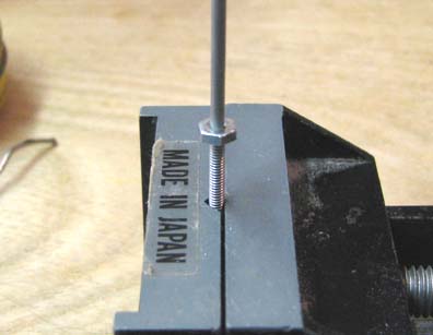
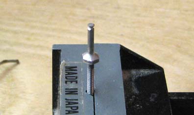
The nut is soldered to the rod and rod is cut off
to length as shown below.
To provide a "bulb" on the end of the rod, a
Dremel cut off wheel is used to cut a groove around the end of the rod as
shown below.
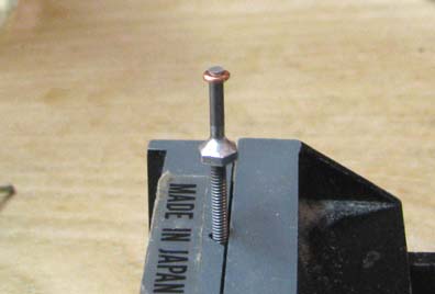
A loop is formed out of a piece of 20 gauge
copper wire and cut off. The loop is squeezed around the rod in the groove
with point nose pliers as shown below.
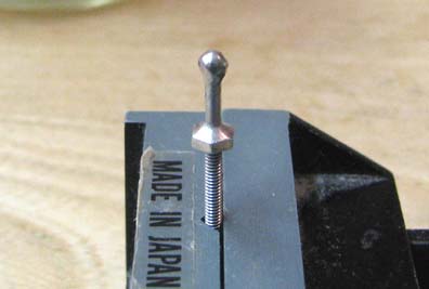
The copper wire is soldered to the rod providing
a bulb for purposes of attaching an alligator clip to and having it stay on
the pin.
The two external pins are threaded in the blind
nut hard points in the hatch cover and jam nuts are used lock the pins in
place. Then wire terminals are bolted onto the external pins as shown below.
This shows the external pins from the outside of
the hatch cover.

I got two very good suggestions today. First,
Thomas Ryan suggested that: "you
could also cut the 2nd knurl of the knob off", which of
course would reduce the weight out at the end of the needle valve stem by at
least half. Now why hadn't I thought of that? (Thank you Thomas)
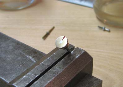
Using a Dremel cut off wheel, I carefully made
several cuts around the knob until I got it cut in half as shown below.
The
second suggestion came from Alfredo Herbon: "Important detail, do not
forget to file a notch into the brass knob to visualize easily the needle
valve setting. Lastly I'm using a dot of red paint in the notch ...,"
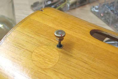
So after filing and polishing the exposed end of what
remained of the brass knob, I did in fact file a notch on one side and fill
it with red paint as shown below. (Thank you Alfredo)
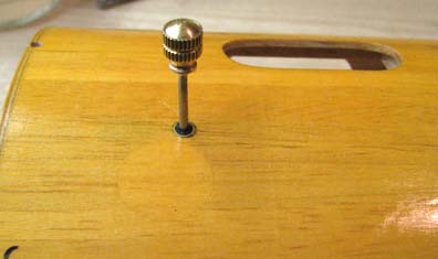
The picture below now shows what the exposed
needle valve looks out side the cowl...................Tandy