Yesterday I began the final assembly of the
Sailplane. However, I worked too late to get my report out, so I am posting
it this morning.
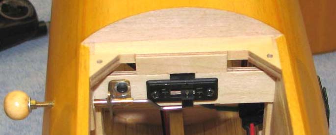
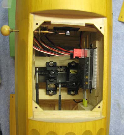
The picture below shows the internal radio switch
that is operated from outside the fuselage. I wanted the switch on the
right side of the fuselage so it would be accessible. By putting the switch
inside, it is protected from the engine exhaust. You can just see the edge
of the radio's charging jack mounted externally on the left side of the fuselage
(right side of picture)
opposite to the side of the engine's exhaust.
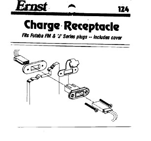
I use Futaba radio equipment with "J" series
connectors in most of my models. Futaba never had a mounting fixture for
the charging jack on its switch harness. However, as most of you know, a
company named "Ernst" makes the No. 124 for the Futaba "J" series
connector as shown below.
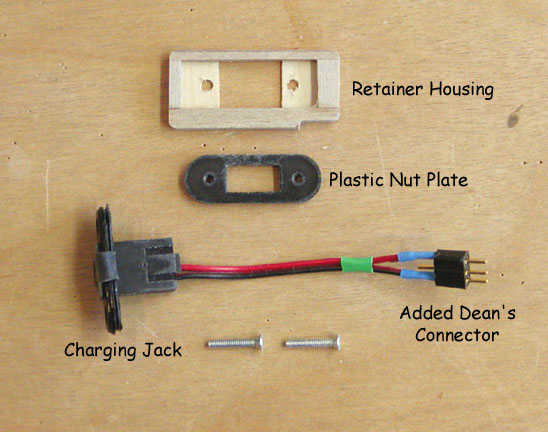
There are two problems with the Ernst Charge
Receptacle: (1) once you get the male J connector inserted into the
receptacle, it is almost impossible to get it out, which is necessary if
you want to remove the switch harness from the aircraft and (2) I have
always had a problem getting the plastic nut plate onto the receptacle
body from inside the fuselage. So on this Sailplane radio installation, I
decided to solve both of these problem as illustrated below. I cut the
charging connector line on the Futaba switch harness in half and installed
a Dean's connector, which is easy to plug in and unplug. This eliminated
problem (1). Next, I made a wooden retainer housing out of 3/32" plywood
that positions and holds the plastic nut plate in place inside the
fuselage.
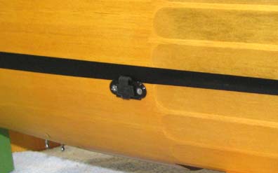
This picture shows a left side view of the
Ernst charging jack.
The radio's 500 mAh NiCad flat battery pack is
mounted on a Velcro plate, which is screwed to the top of the radio
compartment as shown below. The small loop you see is to assist in working
the battery into position under the servo mounting beams.
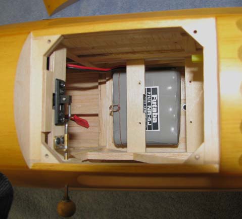
Looking down into the radio compartment, you see
the rudder servo mounted on the right and the elevator servo on the left
over the battery with the Futaba 2.4 gHz FASST receiver mounted on
the side. This is a compact compartment, which has to go together in a very
specific sequence.
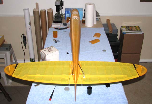
This picture shows the Sailplane's tail assembly
attached to the fuselage on the work table.
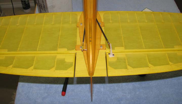
This is a close up view of the two push rod
connectors
attached to the rudder and elevator control horns.
I spent a little time setting up
the new Futaba 7C transmitter to achieve the desired control
deflections as well as programming the exponential functions for both the
rudder and elevator.
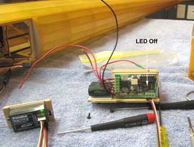
I hooked up the integrated ignition unit
containing Marv Stern's Aero Tech IGN-SW ignition module to the receiver
external to the fuselage as shown below to work out its operation. Notice
that LED indicating the Aero Tech IGN-SW ignition module is off when the
transmitter throttle is off. this indicates that the ignition system is inactive.
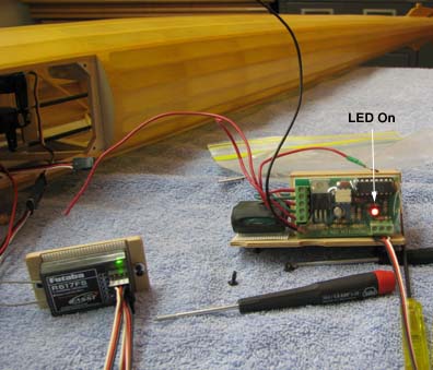
By advancing the throttle on the transmitter from
off, to slightly past midway of its travel, the LED came on instantly,
indicating the ignition system was then active. Marv's unit is nothing less
than outstanding in both its size and functionality. At this point, I
stopped work and got ready for bed.
Today I plan to continue the final assembly of
the Sailplane......................Tandy