Comet
Sailplane Project
In order to determine the pylon location relative
to the fuselage, the wing off balance must be determined by installing the
available parts and equipment in the fuselage. First I needed to make the
wire tail skid and install it in the sub rudder as well as make the rudder.
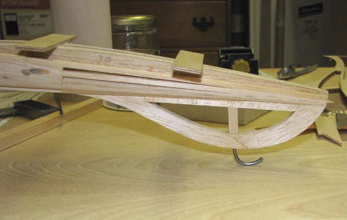
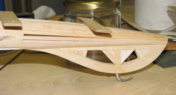
The proper shape of the bent end of a piece of
3/32" piano wire for a tail skid was determined by a trial fit in the sub
rudder with the fuselage up on its main landing gear as shown below.
Notice how the arch of the wire is tangent to the surface of the table
top.
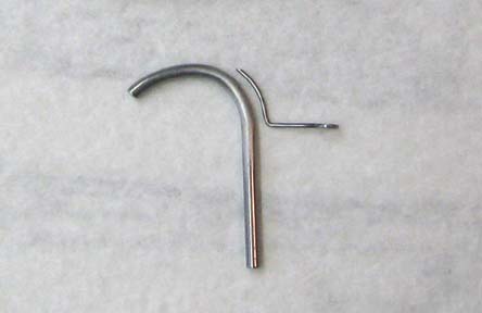
The 3/32" piano wire tail skid is shown below.
To stabilize as well as retain the tail skid in the sub rudder, a piece of
1/32" piano wire with a loop on one end is used as shown below.
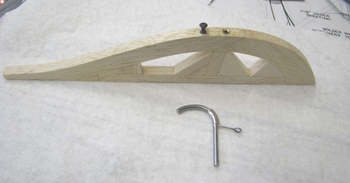
The piece of 1/32" piano wire with a loop on one
end is attached to the tail skid by wrapping it with fine brass wire and
soldering as shown below. A hole is drilled in the edge of the sub rudder
and a piece of brass tubing is epoxied down inside to receiver the straight
portion of the tail skid. The threaded portion of a 2-56 control clevis was
cut off for a threaded boss and also embedded in the edge of the sub rudder
with epoxy. A 2-56 cap screw is threaded into the boss in the edge of the
sub rudder as shown below.
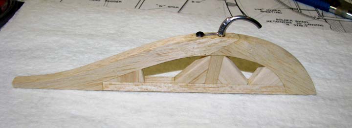
This picture shows the straight portion of the
tail skid slipped down into the brass tube in the edge of the sub rudder
and stabilized as well as retained with the 2-56 cap screw. Notice that
the sub rudder structure has been beefed up four 1/4" gussets to take the
ground loads and moments that will be induced through the 3/32" piano wire
tail skid.
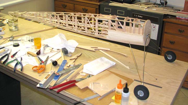
The picture below shows the landing gear
installed on the fuselage for the trial fit of the tail skid.
This picture shows the finished tail skid
installed in the sub rudder on the fuselage.
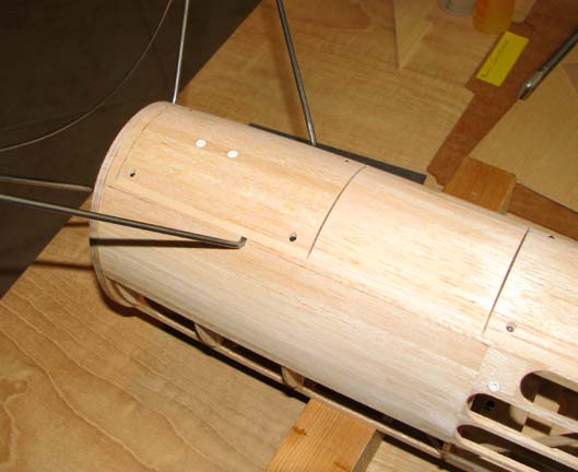
As a point of interest, this is the first picture
that shows how the forward ignition hatch cover closes in the rear 1/8"
strut of the wire landing gear.
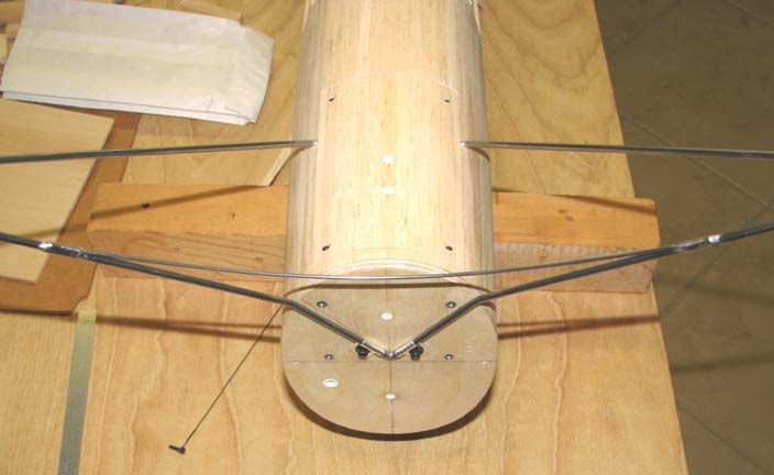
Here is another view from the bottom front.
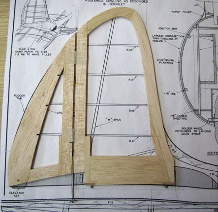
In closing, the picture below shows the new lay
up of rudder. The internal rib and spar structure of the fin and rudder will
come later after the fin/stab/fuselage fillets are worked out.
The plan is to now install these available parts,
radio equipment, engine/tank/mount, and prop on the fuselage and then
determine the wing off balance point...........................Tandy