Click Here to return
to the Index
Sailplane Construction Project Session #5
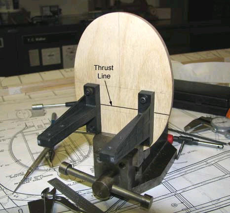
Shown below are the Carl Goldberg composite T-Mounts mounted to the Sailplane's (SP) firewall along with the vertical location of the thrust line.
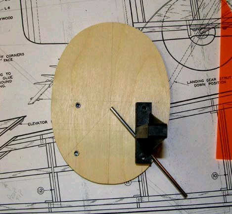
The picture below shows how the forward landing
gear 1/8" right leg (looking aft) will be positioned on the 1/4" plywood
firewall behind the composite T-Mount. A 1/2" square spacer goes between
the T-Mount and the firewall and has an 1/8" inclined slot that will trap
the lower portion of the 1/8" piano wire against the firewall. Of course
there will be a metal clip bolted to the firewall at the apex to further
secure the 1/8" piano wire to the firewall.
Here is the 3-view drawing of the spacer on the
right. Of course the inclination of the 1/8" slot is reversed on the left
spacer as Note (b) points out. I am currently trying to get these spacers
machined out of aluminum.
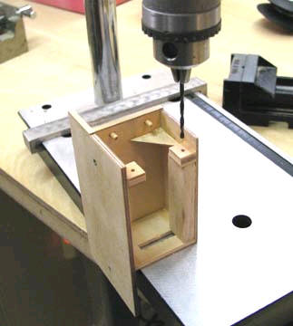
For the last couple of days I have been working
through the details of a design for the SP's ignition system that integrates
all of the system's components into a single package or unit. The back side
of the unit is shown below under the drill press. The two small plywood tabs
are being drilled out for holes to be tapped with 2-56 threads.
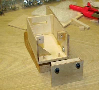
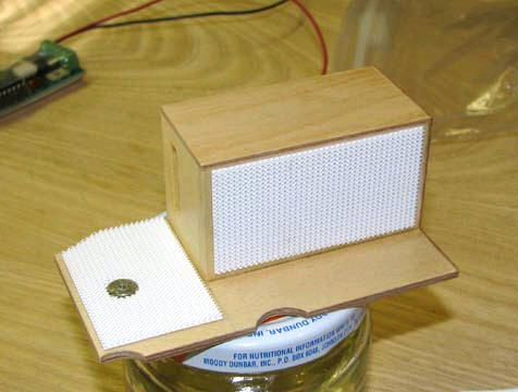
This view shows the unit's compartment for the
ModelElectric coil with the removable end in the foreground.
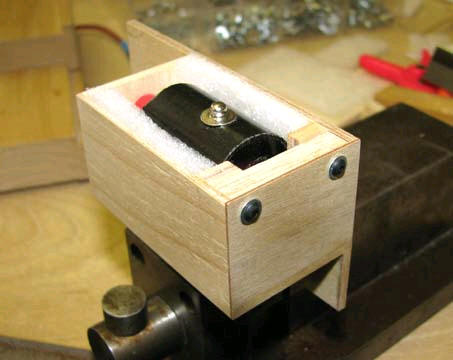
Here the ModelElectric coil is installed in foam
in unit's coil compartment.
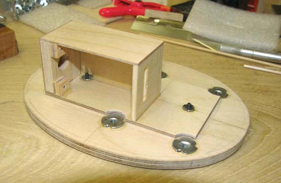
This shows the unit bolted to back of the SP's
firewall. Notice the clearance cut outs in the unit's base for the T-Mounts
6-32 blind nut flanges on the back of the firewall. Notice also the larger
hole in the removable end that secures the coil in the unit's coil
compartment.
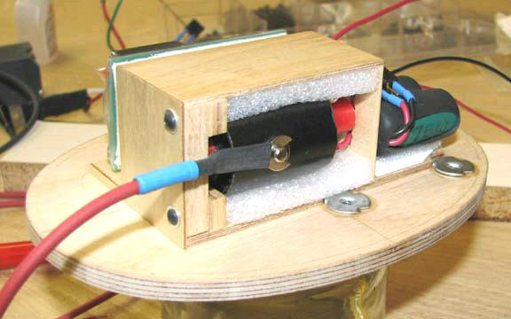
The wood on this unit was given five coats of
clear doped to seal all of its surfaces. Then Velcro was applied to back
side of the unit's coil compartment for shock mounting Marv Stern's Aero
Tech IGN-SW ignition module and to the unit's base in front of the coil
compartment for shock mounting the 3-cell ignition battery as shown below.
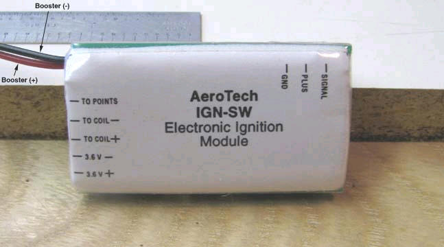
Here is a picture of the underneath side of Marv
Stern's Aero Tech IGN-SW ignition module with the wiring instruction shown.
Notice this is one of Marv's earlier modules retrofitted with wires for
booster battery capability as shown below. The black "Booster (-)" wire is
module's common ground that is connected directly to the engine.
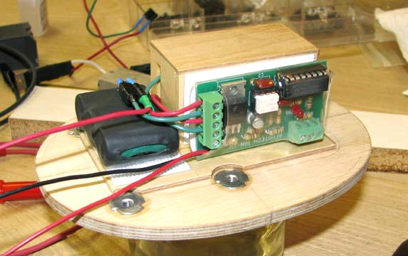
This is a nice shot of the Aero Tech IGN-SW
ignition module and the 3-cell ignition battery installed on the unit and
partially wired up.
This is a view of the unit's other side showing
the ModelElectric coil installation. This design makes for a nice clean
compact removable ignition system that can be easily removed as a single
unit through a hatch in the bottom of the SP's
fuselage............................Tandy