Comet
Sailplane Project
I decided to use my standard method for the
hinge wire retainer on the fin/rudder, except that I used a smaller 0-80
screw for the first time (I
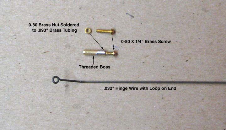
generally use a 2-56 screw). First, I bent a small
loop on the end of a piece of .032" piano wire with a very hole diameter
that a 0-80 screw would just slip through. With a second bend, this
formed the continuous hinge wire shown below. Next I soldered an 0-80
brass nut to a short length of .093 brass tubing to form a "threaded boss"
also shown below.
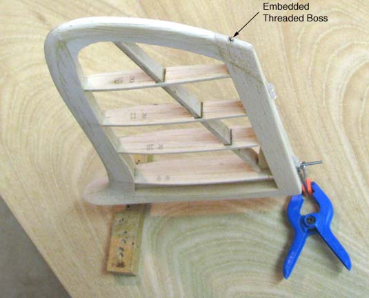
I located the position of the hinge wire loop
on the top edge of the fin and carefully hand drilled an .089" hole in
the edge of the fin with a No. 43 drill bit. The inside of the hole was
coated with epoxy as was the outside of the .093" brass tube and then the
threaded boss was pushed into the hole in the edge of the fin and the
excess epoxy was wiped off with alcohol as shown below.
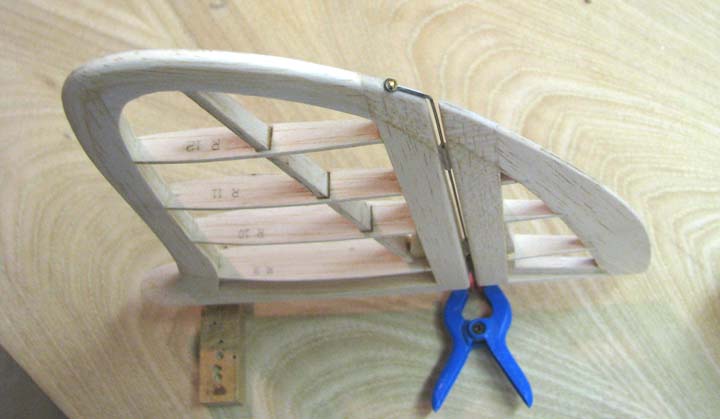
Once the epoxy had cured, the continuous hinge
wire was inserted down through the hinge halves, which coupled the rudder
to fin as shown below. The final step of course was to screw in the 0-80 X
1/4" brass screw onto the threaded boss to retain the hinge wire.
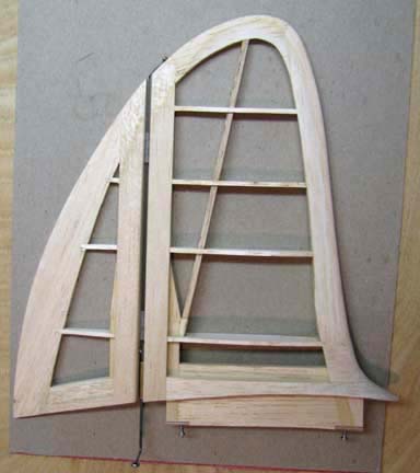
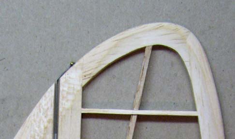
This picture shows the planform view of the
vertical tail
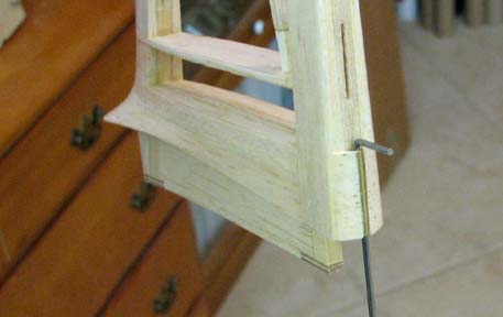
This is a close up of the hinge wire retention
screw.
I did one additional thing to reinforce the
rudder tiller's brass tube bearing at the base of the fin's trailing edge.
I glued in cross grain balsa fillets on either side of the brass tube as
shown below.
This completes the vertical tail except for
covering. I got to again put the project aside for several days and
actually start our taxes this time, so there will be no more Sailplane
construction reports for a while.....................Tandy