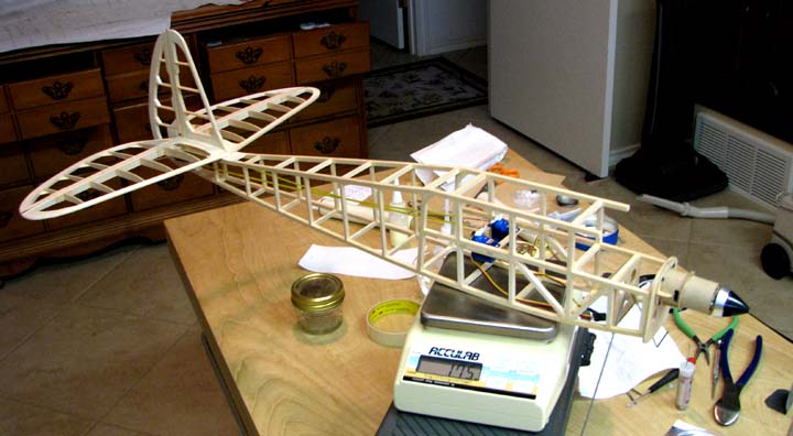
Speed 400
Cloudster Project
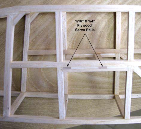
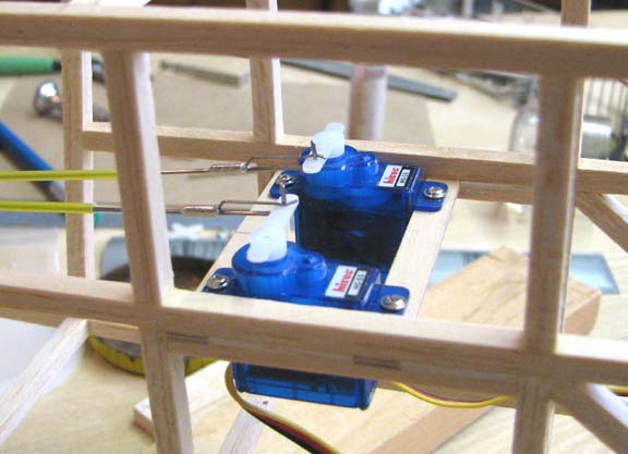
Looking in from the
right side of the fuselage main frame, you can see the ends of two 1/16" X
1/4" plywood servo rail mounts secured in place with a sandwich structure.
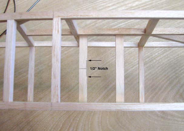
Looking down from
the top of the cabin, notice the 1/2" notch on the forward edge of the aft
rail.
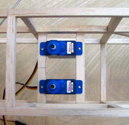
The small light
weight Hitec HS-55 servos shown below were selected for use on the Cloudster.
The servo rail mounts are placed to touch each end of the servo. Therefore,
to remove the servo, they are slid over to the center where the notch is
located, lifted up, and then tilted to get the servo out from between the
rails. It is because the servo wire and connector prevents the servo from
being lifted straight up out of the rails.
(Good Tip!)
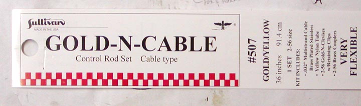
A very good friend
of mine and outstanding model builder who won the SAM Championship several
times, was Jim Reynolds of Universal City, Texas down by San Antonio. Jim,
who is gone now, showed me how to make extremely light weight push rods,
which I have used many time, using Sullivan's Gold-N-Cable #507 shown
below. He told me to use the yellow sheath as the guide and substitute 1/32"
piano wire as a push rod for the 1/32" stranded cable that comes with the
set.
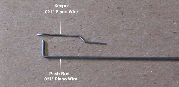
I came up with a
neat little clip design to hold the 1/32" piano wire on the servo control
arm that I will now describe using the picture below. A 90 degree bend is
put on the end of the 1/32" (.032") wire to form a push rod post as shown on
the bottom. The keeper, shown on top, is bent up out of .021" piano wire.
Notice that the keeper has "V" bent on the end that fits up around the push
rod post.
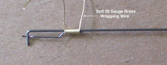
The keeper is
attached to the push rod by wrapping the two together with soft 28 gauge
brass wire as shown below.
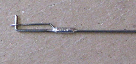
Care must be taken
in getting the keeper properly aligned so that the V on the end engages the
push rod post. Then to complete the clip, the wire wrapping is carefully
soldered in place as shown below.
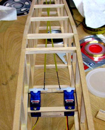
The two push rods
are clipped onto the two control arms of the installed servos as shown
below. Notice that the V keeper is place on the inside of the push rod post
so it can not possible come off.
This picture shows
how the push rods cross as they go back down the fuselage main frame in
order to keep the push rods as straight as possible. To complete the push
rod installation, both yellow sheaths must be braced (stabilized) at least
every three inches. On the Cloudster, a brace will be added at every other
station in the fuselage main frame.
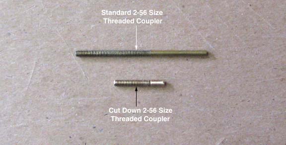
The 2-56 brass
coupler for the Sullivan clevis comes much too long and heavy for this
application. So as part of the Cloudster's on going weight saving effort,
both ends of the coupler are removed using a Dremel cut off wheel. As you
can see, the length and weight of the couple is cut in half as shown below.
However, There are still enough threads on the short couple for two complete
adjustment turns in either direction.
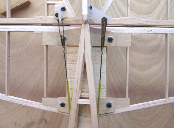
The picture below
shows how the two push rods exit the aft end of the fuselage and attach to
the rudder and elevator control horns. You can see that by cross the push
rods in the fuselage the push rods can remain essentially straight.
Before quitting for
the day, the Speed 400 motor was mounted to the fuselage assembly which was
weighted as shown below. The weight so far is now 175 grams (6.17 oz) and
the model CG is still right where it should
be..............................Tandy