Speed 400
Cloudster Project
In order to lay out
the wing's right inner panel, the dihedral and polyhedral inclination jigs
had to be made. From Report No. 33 it was determined that the polyhedral
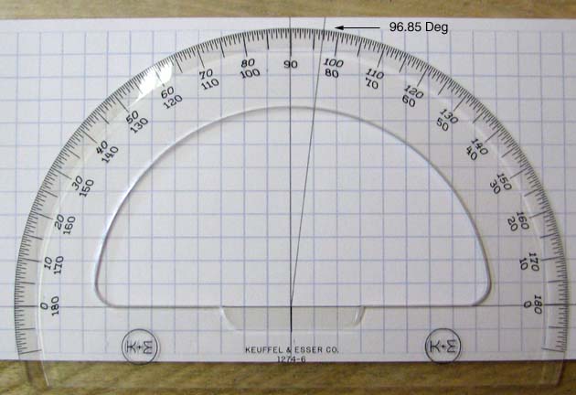
break angle was 13.701 degrees. It is my custom to put half of this angle
(13.701/2 = 6.85 degrees) on the end of the wing's inner panel and half on
the end of the wing's tip panel. Since this angle is beyond 90 degrees, the
angle of the inclination jig is 90+6.85 = 96.85 degrees. This angle was laid
out on paper with a protractor as shown below.
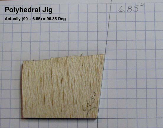
Then
using a piece of 3/16" balsa, one edge of the polyhedral inclination jig was
cut and sanded to the proper angle as shown below.
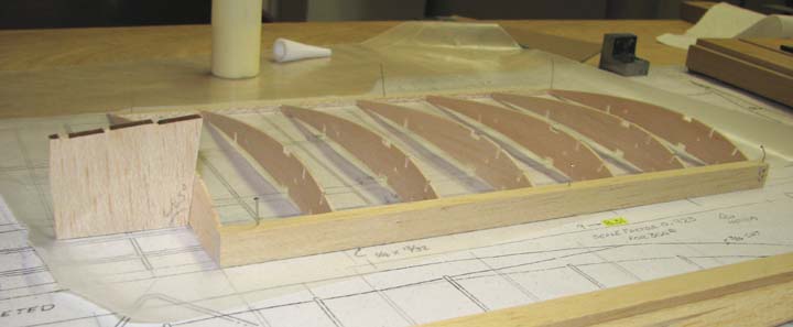
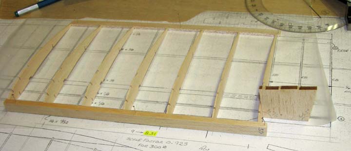
The
1/4" X 1/2" leading edge and the 1/8" X 1/2" trailing edge were pinned down
on the right wing's inner panel. Then five of the R1 ribs were glued in
place 90 degrees to the plan. The jig was used to set the inclination of the
temporary polyhedral rib on the end of the inner panel as shown below.
Again from Report No. 33, it was determined that the dihedral break angle
was 6.76 degrees. Since this angle is small, the total angle was applied to
the root of the wing's inner panel. Using same piece of 3/16" balsa, the
other edge of the inclination jig was cut and sanded to the proper angle
(96.76 degrees) and used to set the inclination of the inner panel's root
rib as shown below.
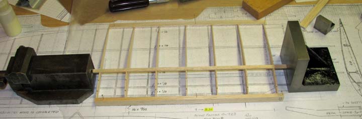
The
main 3/32" X 1/4" top spar was placed in the rib cut outs without gluing.
Heavy steel abutments were placed up against end of the spar to hold it in
place spanwise. Then a small steel block square was used to check and adjust
each R1 rib to 90 degrees on the main spar. Only the five R1 ribs were
tacked in place with a drop of medium CA. Then the two inclined end ribs
were checked with the inclination jig and tacked in place with a drop of
medium CA.
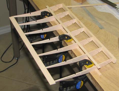
The wing's inner
panel was removed from the plan. It was placed upside down on the work table
and the top spar was clamped in three places with Quick Clamps. This is a
measure to insure that the inner panel remains straight while the bottom
main spar is glued on. Only the five R1 ribs were tacked in place with a
drop of medium CA.
The inner panel was placed back on the
plan and the two end ribs were checked with the inclination jig before they
were glued to the bottom spar as shown below.
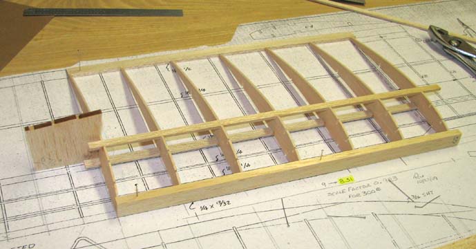
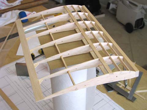
After the rear bottom 3/32" X 3/16" spar
and the three 1/16" X 3/32" turbulator spars were glued in place, all of the
spars were trimmed off and the temporary polyhedral rib bar sanded smooth.
Again, the inclination of the temporary polyhedral rib was checked using the
jig as shown below. This was also done on the inner panel's root rib. Notice
also that 1/16" gussets have been added to the outboard side of the
rib/trailing edge joints to strengthen the joint.
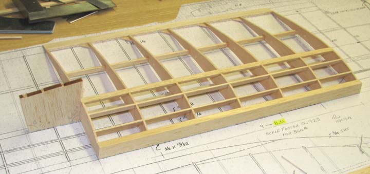
The picture below shows the wing's
completed inner panel, except for the modification of the leading edge at
the root.
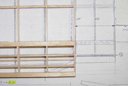
The picture below shows how the leading
edge curves in at the root to mate with the center section. The wing will be
built with a false straight leading edge until the center section's main
spar carry through is completely assembled for accuracy purposes. Then this
portion of the leading edge will be cut away and modified as per the plans
below.
The wing's right tip panel will be built
next. However, tomorrow is Christmas Eve and all modeling has to stop as Sue
and I are having many guests and activities both tomorrow as well as
Christmas day. so I will not get started on the right wing's tip panel until
Saturday. So until then,....................
MERRY CHRISTMAS TO YOU
ALL
Sue and Tandy