Speed 400
Cloudster Project
Wing tip
panels have always been a challenge. Getting the spars and tip ribs to
transition and taper down out at the tip is difficult and mostly an art
form. It is always kind of a guess as to how much to curve the top spar down
or the bottom spar up out at the wing tip. However as shown below, the Jim
Adams plans specify that the wing tip pieces glued together as a unit are to
be shimmed up 1/4", which scales to (.923 X .25) = 0.231".
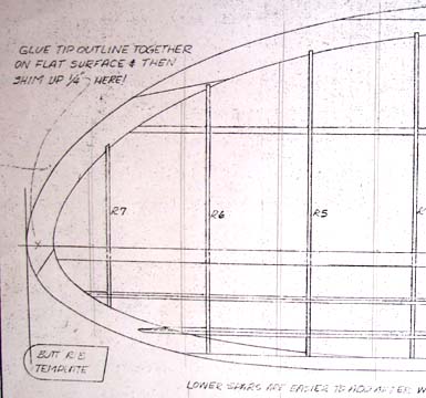
Therefore, it
was thought that the tip panel was going to be easy on the Cloudster wing.
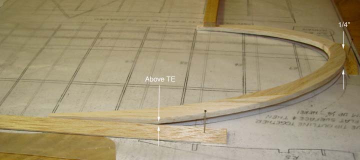
It turns out that this couldn't have been more wrong as shown below. When
the wing tip pieces glued together as a unit are shimmed up, the unit does
not mate (interface)
properly with the trailing edge, so the question is what to do?
Referring back to the insert of
the front view of polyhedral wing on the Cleveland Cloudster plans below, it
can be clearly seen that the bottom surface of the wing tip panel remains
straight and the top surface curves down to meet the bottom surface at the
tip.
When the leading and trailing edges are
pinned down on the plan in an attempt to accomplish this, the wing tip unit
can not also be flat on the plan. You see due to the wing's undercamber, the
bottom spar is elevated off the plan and will not tie into the tip unit
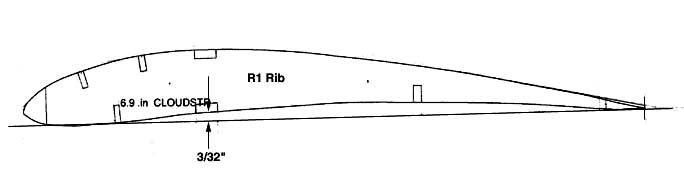
properly. The solution to this problem can be addressed by looking at the R1
rib pattern below. First, the bottom spar is elevated 3/32" off the plan. By
shimming the bottom of tip unit up 3/32" off of the plan at the tip, the
bottom spar can be straight as well as flush with the tip unit at their
intersection and the bottom surface of the wing tip panel will remain
straight.
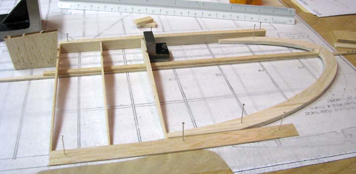
In the picture below, the leading and
trailing edges have been pinned down and the first three R1 ribs have been
glued in place, with root rib inclined at 96.85 degrees. The wing tip unit
has been elevated 3/32" at the tip and glued in place. The 3/32" X 1/4"
bottom spar has been put in place with a 3/32" spacer put underneath such
that the bottom spar is flush with the tip unit at their intersection.
From this point on, the remaining tip
ribs will be glued in place and then the top 3/32" X 1/4" will be installed
and bent down into place.....................Tandy