Speed 400 Cloudster
Project
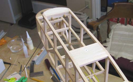
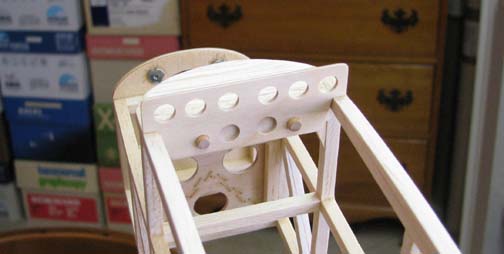
In order to interface the wing's forward
hold down plate with the fuselage, second 1/16" plywood plate was made and
two 3/16" holes were drilled for the two dowels that slide into the hold
down plate. As shown below, this was glued into the top of the fuselage
primary structure. The two 3/16" dowels have been cut to length, shaped, and
slipped into the holes, but not yet glued in. Notice the two dowels are
rounded on the ends. As a side note, since there is no front adjustment to
pull the wing down tight against the fuselage structure, a good close
tolerance fit must be achieved.
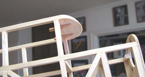
This picture shows the forward portion of
the two dowels cut off at an angle as per the plans.
Here you can see the 2-56 cap screw
threaded into a blind nut embedded in a strip of 1/16" plywood underneath
the 1/8" balsa. If you look close, you can see that a piece of white ABS
plastic tubing lines the hole to serves as a grommet to protect the edge of
the hole around the balsa.
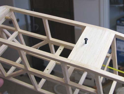
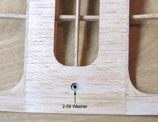
In order to protect the edges of the hole
in the wing's plywood rear attachment, a small amount of medium CA was
carefully applied around the hole in the plywood, a small 2-56 washer was
slipped through the top planking and placed down onto the plywood as shown
below. A 2-56 cap screw was inserted and tightened down to hold the washer
in place until the CA dried.
This is a view from underneath showing
the two dowels engaged in the front hold down plate and the 2-56 cap screw
threaded into the blind nut. Notice the curved gapped opening over the top
longeron resulting from the wing's undercamber.
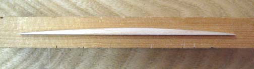
A piece of 3/16" balsa was cut out and
carefully sanded to shape as shown below to form the wing saddle that will
fit into the opening and interface with the wing's bottom planking.
This shows the wing saddle piece glued to
the left top longeron under the wing.
At this point, a problem was realized!
You see in order to remove the wing, it must be slid back 5/16" to disengage
the hold down plate from the two dowel. However, the wing will ramp up as it
starts to slide back along the wing saddle and the hold down plate will
instantly bind on the two dowels! Fortunately, the two dowels had not been
glued in place so they could still be removed. New shorter dowel were made
with almost flat ends as shown below.
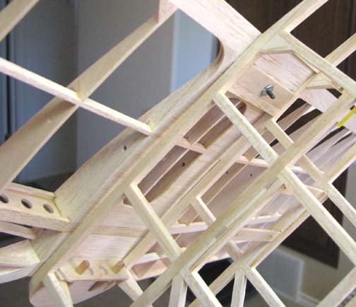
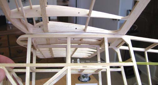
In this view under the wing, you can see
that the new dowels only extend through the wing's hold down plate 1/16",
which allows the hold down plate to cleanly disengage with only a slight aft
movement in the wing while also rotating the wing trailing edge up slightly.
Several trial wing attachments and removals proved this to be
quite satisfactory.
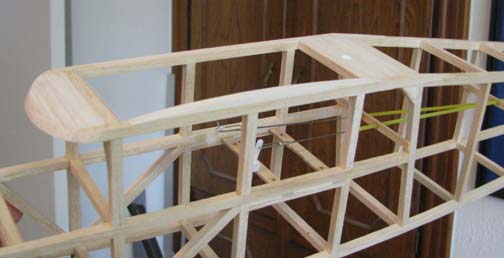
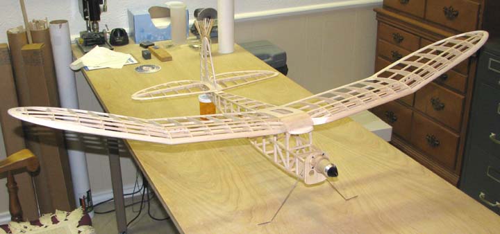
This shows the current Cloudster's
structure from a frontal view. Total weight at this stage of the
construction is (6.17+1.98) = 8.15 ounces, just slightly over half of the 16
ounce minimum weight requirement for the Speed 400 event. The 6.17 ounce
weight was presented in Report No. 25 and the 1.98 ounce weight was
presented in Report No. 47.
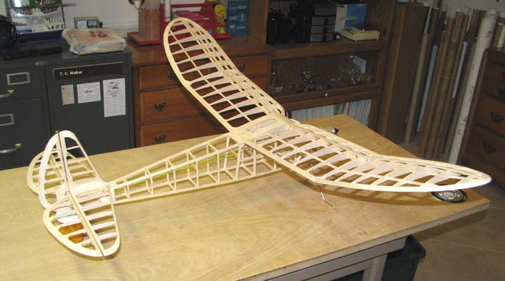
This shows another view of the
Cloudster's structure from the rear.
The wing and tail assembly should be
covered next so that the location of the rather heavy Li-Po battery can be
determined that will balance the model. However, I still have to decide what
the color scheme will be and what covering material to use, which I will
probably have to be ordered. In the mean time, the tail skid can be made and
installed and the fuselage's bottom bulkheads can be cut out. I also need to
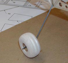
get a set of the lightest 2-1/8" wheels I can find. There are some of these
curved-spoked spider looking wheels for electric models that weigh almost
nothing, but they look simply terrible in my opinion. I may have to resort
to making some light balsa wheels myself like the one shown below that I
made for the little rubber powered Cub I built. Do you know of some light
weight 2" to 2-1/8" wheels?..................Tandy