Speed 400 Cloudster
Project
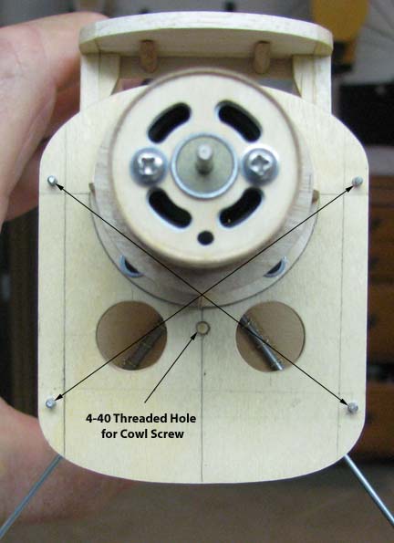
In developing a method for attaching the
cowl to the firewall, the simplest approach was taken using a
single 4-40 "screw assembly", which will be explained later. For the
assembly to be effective, it has to be located so as to apply equal pressure
on each of the four cowl alignment pins. The exact center location is
defined by the intersection of the two diagonals between the four pins as
shown below. However, the threaded hole had to be moved down about a 1/4" so
as not to interfere with motor mount.
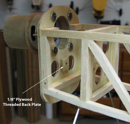
A small plywood square 1/8" thick was
glued to the back of the firewall to provide additional threads for the cowl
screw as shown below. Holes were drilled in the firewall and back plate
separately with a No. 43 bit. The shank of the bit was inserted into the
firewall and used to align the 1/8" plywood square on the back while the
glue dried. Then 4-40 threads were cut through both pieces at the same
time.
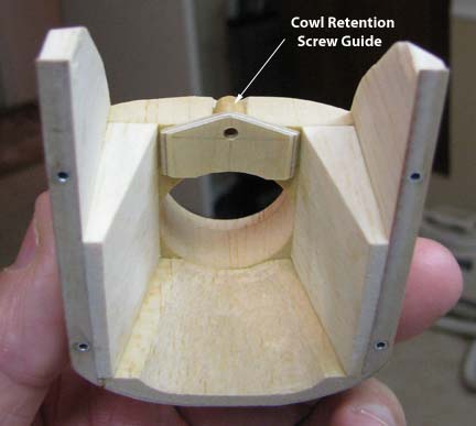
The center of a piece of 1/4" wooden
dowel was drilled out for a 4-40 screw to slide through. This was glued to a
piece 1/16" plywood and the two in combination were glued to the forward
inside face of cowl nose block as shown below. This plywood plate serves as
a strong back for the screw to pull against.
As part of the Cloudster's on going
weight saving effort, a 4-40 screw assembly referred to above was used for
the cowl attachment instead of a long heavier 4-40 metal Allen head screw.
The principal element of this assembly is a 1" length of white ABS plastic
tubing threaded inside each end with 4-40 threads as shown below.
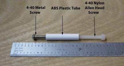
The complete 4-40 screw assembly, which
is shown below, is composed of a short 4-40 metal screw, a 1" length of
threaded ABS plastic tube, and a longer 4-40 Allen head nylon screw. The total
weight is something less than one gram, because on the AccuLab scale, it
reads zero.
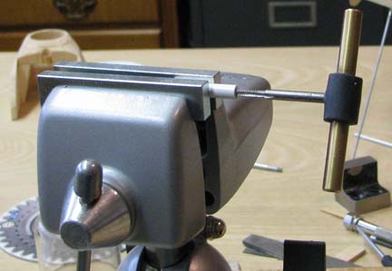
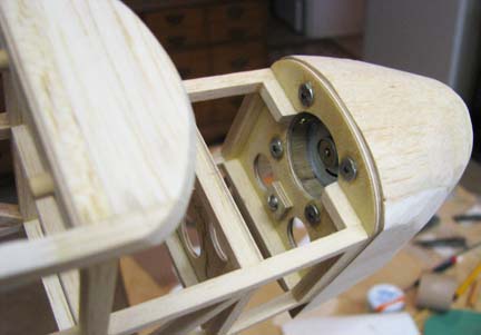
The 4-40 metal screw is screwed in from
the back side of the firewall as shown below.
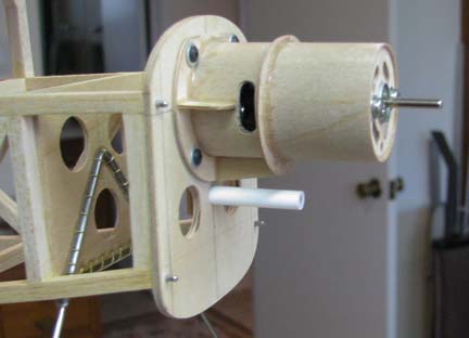
The 1" length of threaded ABS plastic
tubing is screwed finger tight onto the threads of the metal screw
protruding out the front of the firewall as shown below.
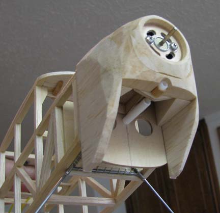
This is a view from underneath the
unfinished cowl. It shows how the cowl is secured to the firewall by
inserting the 4-40 Allen head nylon screw through the cowl retention screw
guide
(the drilled out dowel),
screwed into the open end of the threaded ABS plastic tube, and then
tightened down, which pulls the cowl down snug onto the front face of the
firewall.
I am most pleased with the way this
method for attaching the cowl to the firewall worked out. Now the bottom of
the cowl has to be blocked in with a large opening left in the front to
provide motor cooling air. However, as was said before, carving,
sanding, and shaping of the cowl can not be continued until the bottom
bulkheads and stringers have been added, as well as the curved planking on
the top of the fuselage right behind the firewall. This is necessary to fair
the lines of the cowl into the lines of the fuselage to form the seamless
transition...........................Tandy