Comet Sailplane
Project
I began what I thought was going to be a relative
simple and mundane fabrication of the Sailplane wing's center section. But
as it turned out, the construction was neither simple or mundane! I first
had to make a trip over to Roy's Hobby Shop in Hurst, Texas, to pick up a
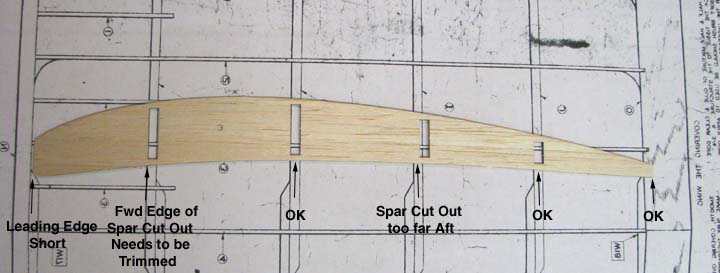
sheet of 5/16" balsa from which to make the leading edge. I used the laser
cut rib No. 3 to check the rib fit with the plans as shown below. As you can
see, the leading edge is too short, the first spar cut out is a little aft,
and the third spar cut out is considerably aft. The second and forth spar
cut outs are OK as is the trailing edge. These misfits must be corrected in
order for the ends of the four spar overlaps and leading and trailing edges
to be correct for the interface with the wing's two inner panels.
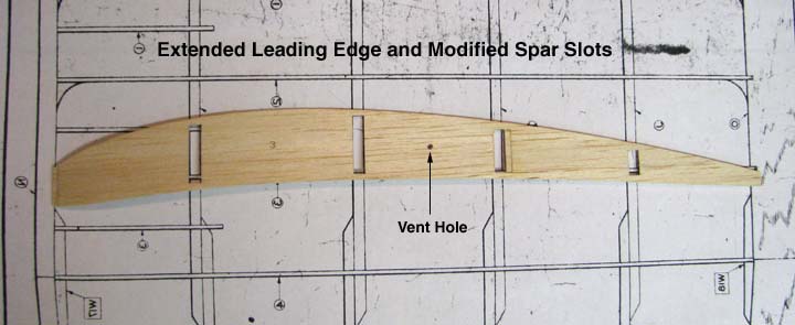
The No. 3 rib was modified to fit the plan as
shown below and a vent hole was added for pressure equalization between rib
bays. This was used as the master rib template to modify the other center
section ribs since the spar cut outs are all the same.
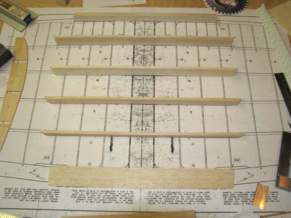
The leading and trailing edges were cut to length
and their ends beveled for the dihedral slope of 4.86 degrees. Bob Holman's
laser cut parts for the Sailplane included all of the tapered spars for the
wing's tip and inner panels. However, since the center section spars are not
tapered, he left it up to the builder to cut his own. As you can see below,
the four straight spars with heights of 1", 1", 3/4", and 5/16" were cut
from medium hard 3/16" balsa sheet and placed on the plan along with the
leading and trailing edges. Notice that all but the first spar has their
ends tapered. The first spar was left untapered for the interface with the
two outer sub ribs.
To insure alignment of the leading and
trailing edges of the wing's left and right inner panels, the inner panels
were pinned down on either side of the center section plan. Then the
center section's leading and trailing edges were pinned in place such that
all of the ends matched up as shown below.
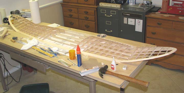
I took this picture to give you a feel for the
size of the Sailplane wing will be.
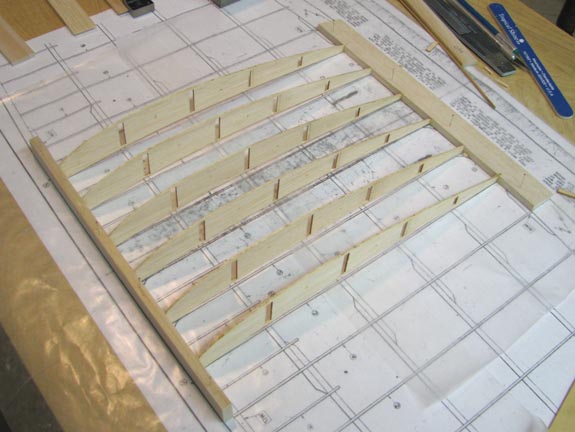
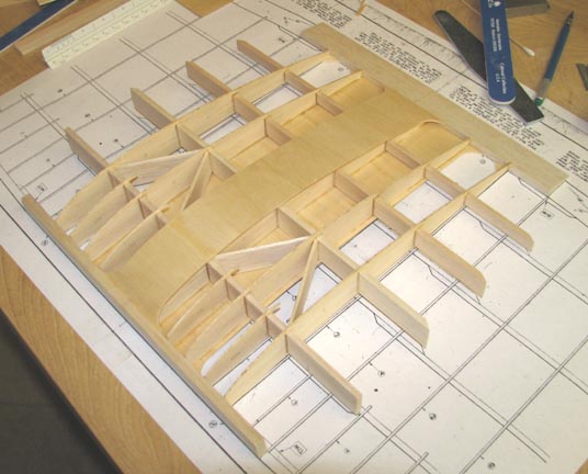
Each of the center section's ribs were glued to
the leading and trailing edges as shown below. These unsupported ribs are
some what weak and flimsy at this point and care must be taken not to break
them until the spars have been added.
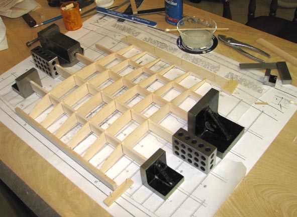
Once the ribs were fully dry, the second 1" deep
spar was inserted and worked down through all of the rib cut outs. The
second spar was positioned over the plan and held in place with steel
squares against each end. Each rib/spar intersection on the second spar was
adjusted over the plan, a square was used to align the rib vertically,
and then it was glued in place. The second spar was installed first to
stabilize the rather flimsy ribs in the middle so that the procedure for the
other three spars would go more smoothly
(this spar-through-the-rib construction takes
considerable time and patience) as shown below.
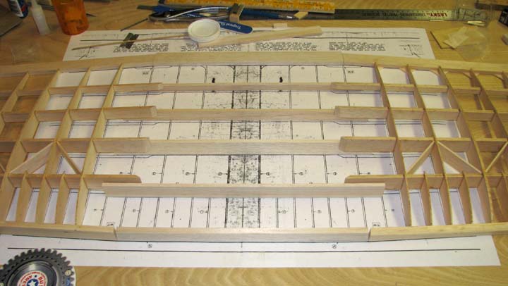
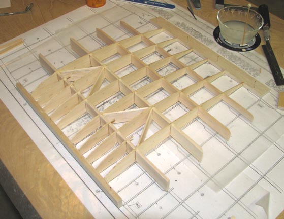
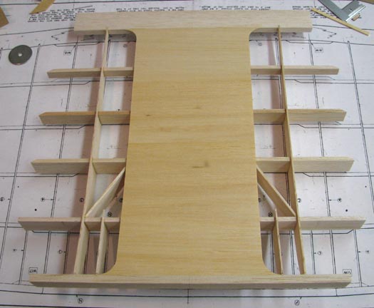
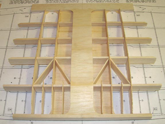
Next sub ribs and diagonals were added the center
section structural frame as shown below. As you can see, there is no
diagonal required in the center bay since the center section is planked both
on top and on bottom with 1/16" sheet balsa. The sub ribs and diagonals on
each end are left off until the wing's inner panels have been attached to
the center section and the dihedral joint completed.
I got into my older balsa supply and found some
6" wide 1/16" sheet balsa for planking the bottom of the Sailplane wing's
center section. It is very consistent in thickness, but a little darker than
the new wood as shown below. I was able to plank the entire bottom section
with only two joints.
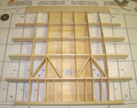
This is view of the bottom planking from the top
side of the center section. As you can see, the bottom planking is quite
wide, extending over three full rib bays according to the plans. This broad
planked area will rest on the rather wide wing saddle.
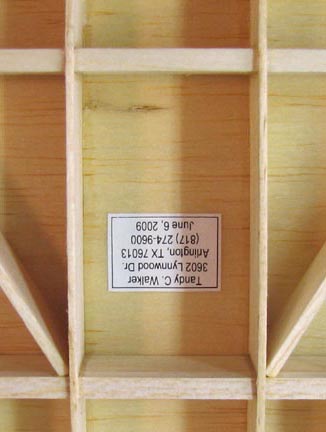
In this close up, you can see that I have a label
with my name, address, phone number, and date glued on the top side of the
bottom planking inside the center rib bay with no diagonal. This
label will be closed up inside when the center section's top planking is put
on. This is like a "Time Capsule".
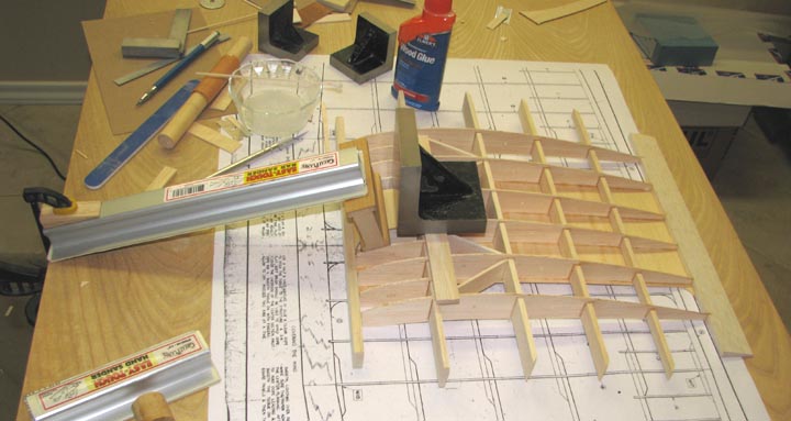
Positioning and gluing the center section's
bottom planking was relative easy as there was open access to the glue
joints from the structure's open top. However, this was not the case with
the top planking. It has to be done in the blind, so to speak, because the
bottom planking prevented any access at all. Therefore, Elmer's aliphatic
glue was applied to the beveled leading edge of the pre-cut planking and to
the top of the ribs after which the 1/16" sheet planking was put in place.
The problem with aliphatic glue of course is that the planking has to be
held down against the ribs until it dries. To accomplish this, support strip
wood was put down and the weight of a large square steel block was used as a
press on top of the planking. In the case of the radius on the leading edge,
I places the slide sander, grit down, on the radius, and used a bar sander
to press on the slide sander. The pressure on the bar sander was achieved
with a slide clamp and a wooden wedge as shown below. Too many words I know,
but the picture illustrates what I am trying to say. The remainder of the
top planking was not a problem because the ribs are only slightly curved
and fairly flat at the back.
The picture below shows the top of the center
section's 1/16" planking completed. The top planking is narrower than the
bottom planking, covering only the center rib bay according to the plans.
This area will support the rubber bands that hold the wing on the pylon's
wing saddle.
Here is a view of the top planking looking in
from the side.
I will now put the center section aside and go
back to work on the right wing panel. The four overlapped glued spars need
to be trimmed, the polyhedral joint rib glued in, and the 1/16" trailing
edge gussets added...................Tandy