Comet Sailplane
Project
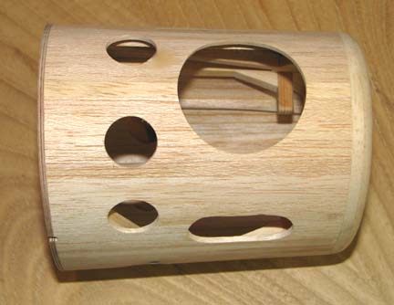
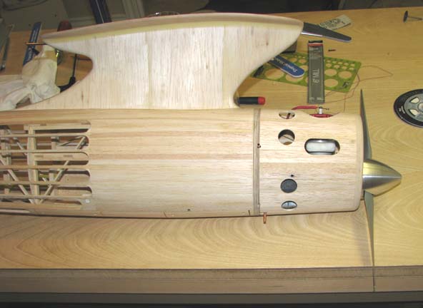
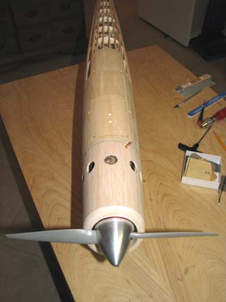
I have spent the day today laying out
and cutting a series of holes in the aft part of the cowl. In addition to
the cylinder and exhaust cut outs for the McCoy 60, this picture below shows
the three exit air vent holes from a top view.
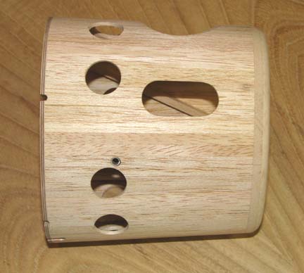
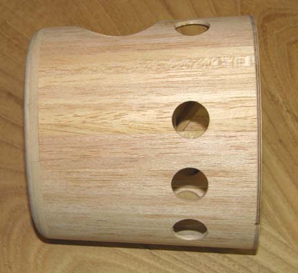
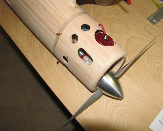
This shows the four holes on the right side of
the cowl in addition to the exhaust cut out. Notice that the four holes are
irregularly spaced.
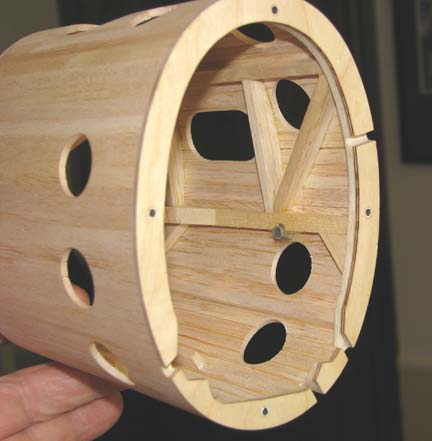
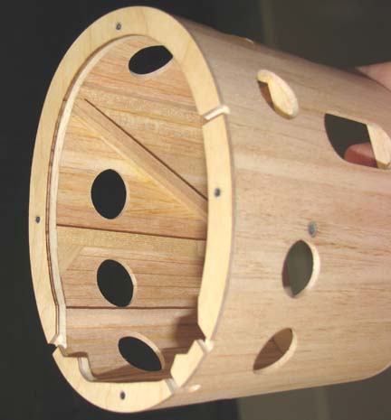
The reason for the hole spacing is to avoid
cutting through the cowl's internal structure as shown from this inside view
of the right side of the cowl.
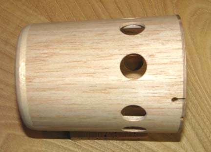
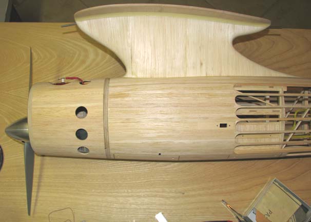
This bottom view shows the three holes in the
bottom of the cowl.
This shows the four holes on the left side of the cowl. Notice that the
four holes are irregularly spaced.
Again the reason for the hole spacing is to avoid
cutting through the cowl's internal structure as shown from this inside view
of the left side of the cowl.
There are nine (9) exit air vent holes in total
and each hole has a 0.8" diameter. So the total exit air vent area
provided by the nine holes is [9 * (Pi/4) * .8 * .8] = 4.5 sq.in.,
not counting what ever additional exit air venting occurs around the
cylinder and exhaust cut outs.
I sent out an opinion inquiry on the adequacy of
these nine holes for exit cooling air flow to several experienced builders.
About 85% of the responses I have gotten back so far felt that the vent
area was not only adequate, but more than enough for engine cooling.
The vented cowl was installed over the engine on
the fuselage and I took the following pictures for you to see.
View of Right Side
View of Left Side
Bottom View
Top View
There is one task left to do and that is build an
exhaust extension to flow the hot exhaust out the cowl's exhaust cut out to
prevent edge burning, which I will do tomorrow. Then I will start the
covering process on the wing and later the
fuselage.......................Tandy