Sailplane Construction Project Session #29
The past several days I have busily developing the
mounting structure for the Sailplane's radio components. I decided to mount
all of the radio components in a single fuselage bay so that one hatch cover
would provide the necessary access.
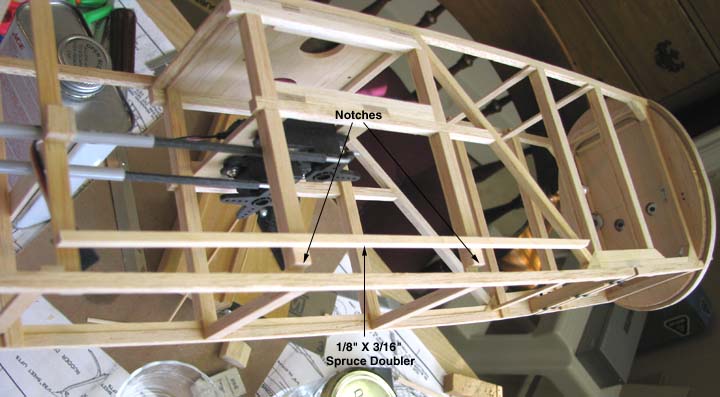
Once again, I became concerned about the
Sailplane's small 3/16" square longerons being strong enough to support the
bottom of the fuselage structure with an open fuselage bay for the radio. so I
decided to put spruce doublers on the lower longerons that would span the bays
on either side of the open fuselage bay as shown below.
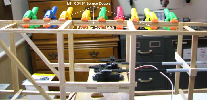
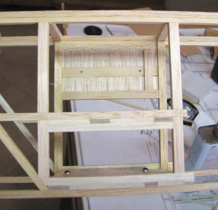
The picture below shows the radio bay open hatch on
the bottom of the fuselage and one of the doublers glued in place on the top
side of the bottom longeron. I have found so many uses for the neat little
colored plastic clamps you see that Bob Beecroft gave me sometime back.
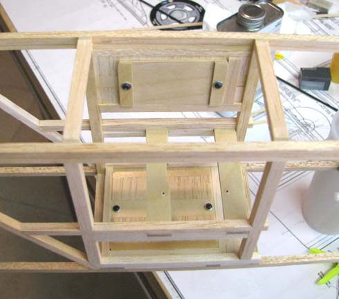
The picture below shows the structure integrated
into the top of the radio bay for retaining the battery pack. Notice the two
1/8" plywood rails going across the top of the fuselage with 1/8" balsa sheet
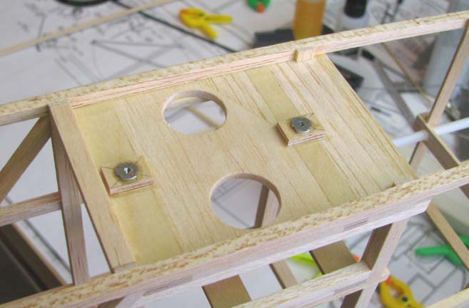
filled in between. In my normal manner, I drilled the two 1/8" plywood rails
and threaded them for 2-56 cap screws. However, later I became concerned about
the threaded plywood holes holding the weight of the battery pack up in the
top of the fuselage on a hard landing. So I came back and added the 2-56 blind
nuts anchored in squares of 1/8" plywood as shown below.
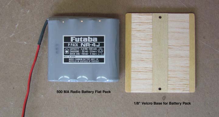
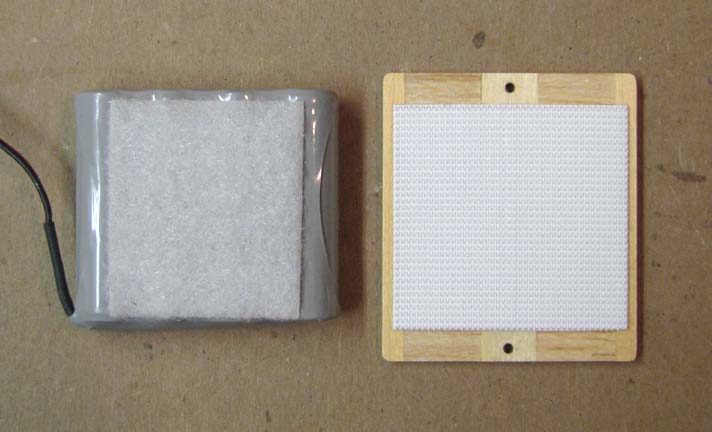
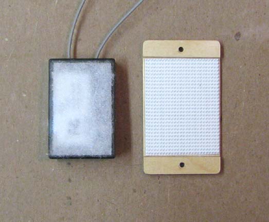
The battery and its Velcro base is shown in the
picture below. The Velcro base is constructed of 1/8" hard balsa sheet with a
plywood strong back running down the center and hardwood edges. It has four
coats of nitrate dope to provide a hard surface to stick the Velcro on.
This shows the Velcro loops on the battery and the
Velcro hooks on the base.
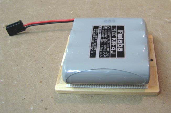
Here the battery is attached to base using Velcro.
This shows the structure integrated into the left
side of the radio bay for retaining the receiver. Notice the 1/16" X 1/4"
strips used to index the Velcro base on the structure.
Here the receiver Velcro base is screwed to the
left side of the radio bay.
This shows the Velcro loops on the bottom of the
receiver and the Velcro hooks on the base.
In the picture below, the battery pack and receiver
are shown installed in the fuselage using 2-56 cap screws.
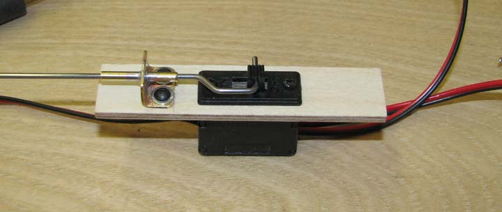
Since the fuselage cross section is elliptical, I
decided to install Futaba's switch harness inside the fuselage with a
push-pull rod to turn the switch on and off. This required the fabrication of
a small brass guide to retain the push-pull rod as shown below.
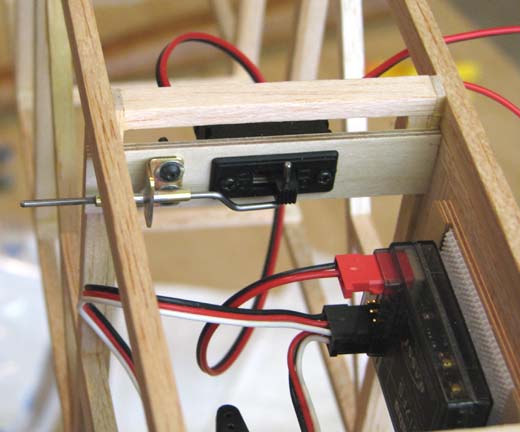
The picture below shows the push-pull switch
installed in the fuselage forward and up near the top of the radio bay. The
end of the push-pull rod will be fitted with a knob on the end for ease of
activation.
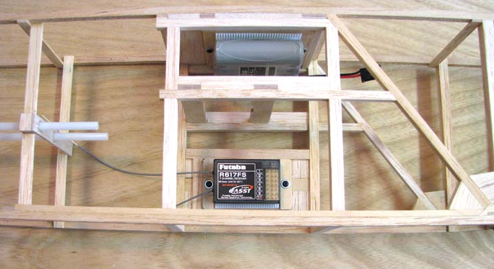
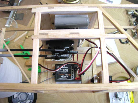
So in conclusion of this report, the battery pack,
two servos, receiver, and push-pull switch are all installed in the single
radio bay of the Sailplane's fuselage as shown below. In this picture you can
see the structure used to secure the plywood mounting cross rails for the
servos and battery pack. Also notice that the structure in this area has 3/16"
X 1/4" balsa strips glued onto the fuselage frame 3/16" X 1/4" uprights.
Getting all of these radio components in and out of the radio bay hatch
opening is a real jig saw puzzle. However, I have demonstrated that it can be
successfully done!..................Tandy
Click Here to go to the
next page (30)....