I got a one week reprieve on
doing our taxes as my wife Sue has a number of "house things" lined up for
us to do such as clean the tile on the kitchen floors and back hall, work in
flower beds, go to the nursery and buy 36 Impatience (SP) plants and plant
them, and shop for some area rugs. Therefore, this turned out to be a
perfect time to solve a troublesome Sailplane problem that I have been
wrestling with for some time.
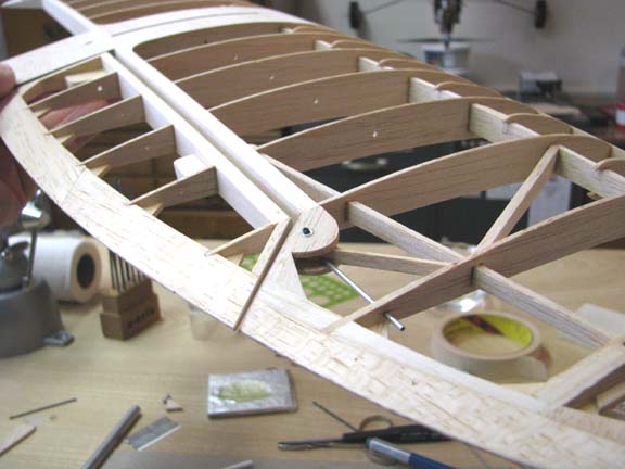
Comet
Sailplane Project
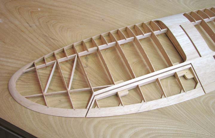
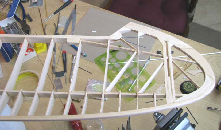
Ever since I decided to slant shape the elevator
tip chord before reaching the tip of the stab as shown below, the retention
of the elevator hinge wire on the Sailplane horizontal tail has remained
unsolved. I have been thinking about this all along, but a design concept
never came to mind until the other night. I was in bed trying to go to
sleep when it came to me.
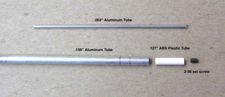
The components of the retention device are shown
below. You need to know that the 1/2" long piece of ABS plastic tubing fits
snugly inside the larger aluminum tube.
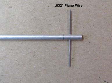
CA was applied to the outside of the ABS plastic
tubing and slipped down into the larger aluminum tube and given a half turn
to spread the CA inside. This bonded the two tubes together. Then
the aluminum/ABS tubes were drilled diametrically through with a .032" drill
bit so that the .032" hinge wire would slide through as shown below. Then
the inner ABS tubing was tapped with 2-56 threads.
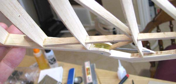
An .063" hole was drilled through the stab's root
chord, diagonal brace, and the next stab rib. A piece of the .032" hinge
wire was slid through the stab hinge and a short piece of the .063" aluminum
tubing was slid onto the hinge wire. This was put through the stab's root
chord and the aluminum/ABS tube slid onto the hinge wire and butted up
against the .063" aluminum tubing. Finally another longer piece of .063"
aluminum tubing was slid through the stab rib, the diagonal brace, and onto
the hinge wire from the opposite direction and butted up against
aluminum/ABS tube as shown below. The CA was very carefully applied to tack
bond everything in place in the stab structure as shown below. The reason I
said carefully was because you do not want the CA to get down between the
butted tubes and bond the hinge wire inside. Now you can clearly see the
design concept for retaining the hinge wire. Once the hinge wire is slid
through the aluminum tubing, the 2-56 set screw is screwed down into the
aluminum/ABS tube thus locking the hinge wire in place. There is significant
friction between the ABS threaded tube and the set screw so vibration will
not loosen the set screw.
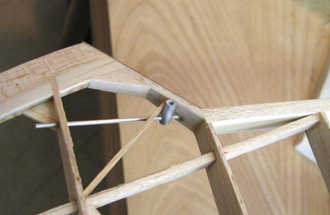
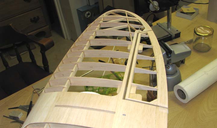
A round piece of 1/8" sheet balsa was glued on
top of the stab structure with the aluminum/ABS tube projecting through as
shown below. Notice the 2-56 set screw sticking out of the top. Also notice
how the .063" aluminum tube was filed down flush with the stab root chord.
Another round piece of 1/8" sheet balsa was glued
on the bottom of the stab covering the bottom end of the aluminum/ABS tube.
To insure that this entire retention device was
locked in place, it was completely "potted" in epoxy as shown below.
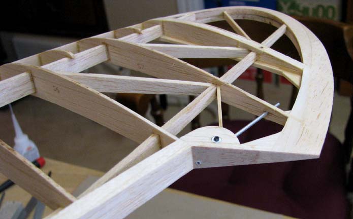
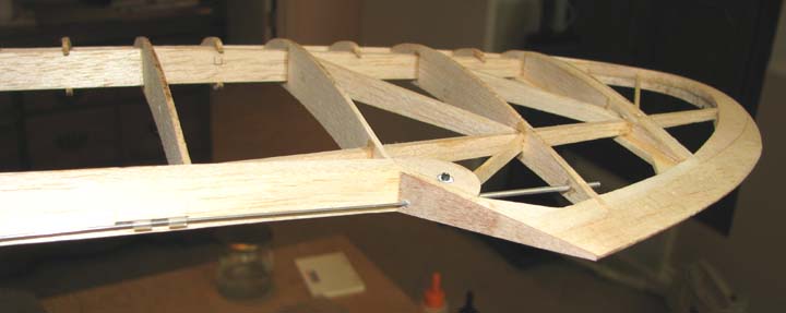
This picture shows the .032" hinge wire in place
without the elevator.
To install the hinge wire, begin by inserting it
through the outboard hinge as shown below.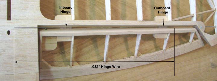
Next push the long hinge wire outward into and
part way through the .063" aluminum tube until the left end of the hinge
wire just clears the edge of the inboard hinge as shown below. Of course the
right end of the hinge wire is inside the aluminum tube.
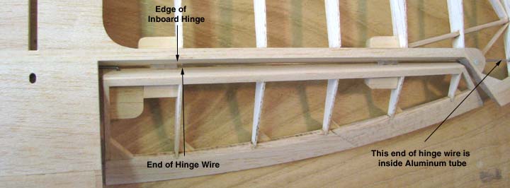
Then using tweezers, grasp the hinge wire
and slide the left end through the inboard hinge far enough so that the end
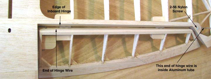
of the hinge wire is beyond the edge of the inboard hinge as shown below.
The hinge wire is locked in place by screwing the 2-56 set screw tightly
down against the hinge wire inside the aluminum/ABS tube. The hole over the
set screw is sealed off by screwing in a short 2-56 nylon screw down against
the top of the aluminum/ABS tube also shown below.
This is shot from the tip of the stab with the
elevator installed.
This shows the whole right side of the stab with
elevator installed. What a lot of work for such a small
device.......................Tandy