Comet
Sailplane Project
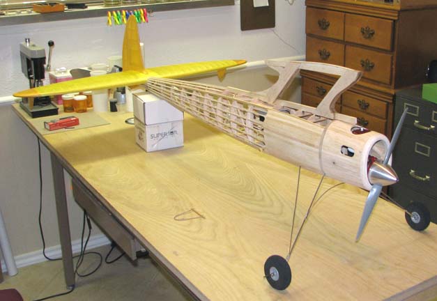
I spent the morning reinstalling the, servos,
push rods, battery, receiver, switch, ignition unit, landing gear, engine,
prop, spinner, cowl, and the complete covered and doped tail assembly along
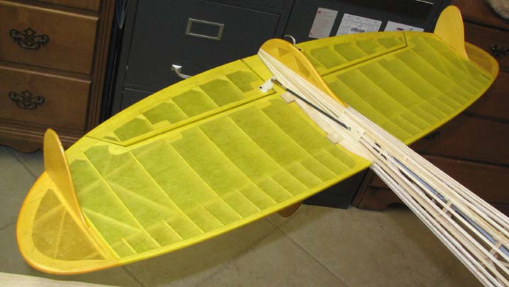
with the sub rudder as shown below.
This shows the top front view.
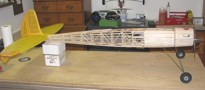
This shows the bottom front view.
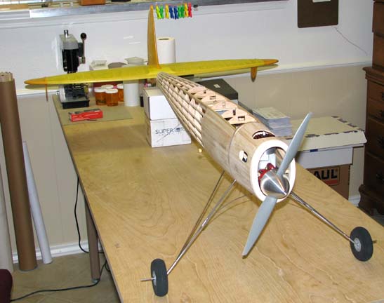
This shows a view of the bottom of the stab and
the sub rudder (not yet glued in).
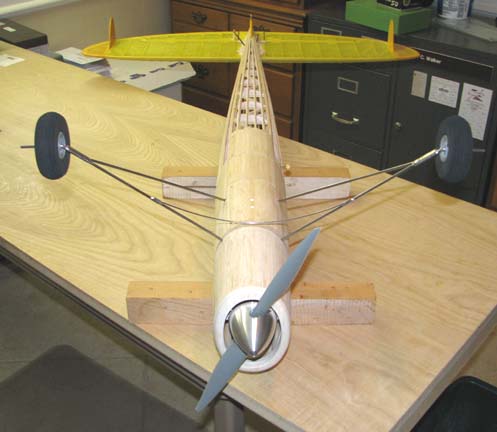
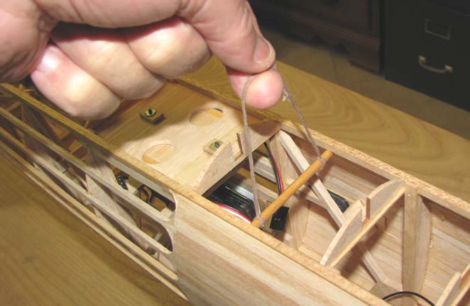
The picture below shows the sling made to
determine the balance point of the model. A piece of 3/16" birch dowel was
cut to length so that it would fit down inside and under the two 3/16" top
longerons. A waxed cord doubled four times was attached to the dowel on
either side and used as a bridle to pick the model up with. As you can see,
the dowel can be slid fore and aft to locate the wing off balance point.
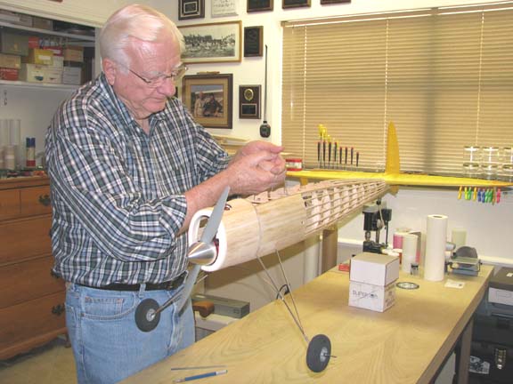
I asked Sue
(my wife) to take this picture with me holding the
sling that is freely suspending the model above the work table with the
model in balance.
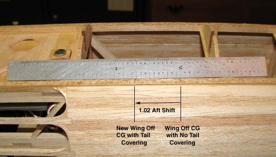
The picture below shows a 1.02" aft shift in the
wing off balance point due to the additional covering and doping of the tail
assembly.
If you recall from Report No. 45, the M1 doubler
on the pylon frame was positioned at the rear face of bulkhead No. 1 (back
edge of the firewall), which is the pylon's most forward on the fuselage
without having to cut into M1 doubler as shown below. Now the fuselage's
wing off balance point is only 0.35" forward of the rib M7 arrow location.
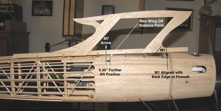
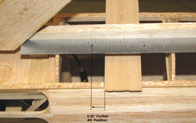
The M7's 0.35" aft position is shown with the
scale below.
Rather than moving the pylon forward, I decided
to leave it at the 0.35" aft position as a contingency or margin on not
being tail heavy. After all I do not have the fuselage double covered and
doped yet which will add some additional aft weight to the fuselage. The
picture below shows where the location of the pylon is going to be on the
fuselage............................Tandy