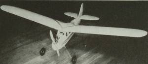
"Project Re-Buc"
By Tommy Gray
AMA 17063
Holidays are past and I am working on the Re-Buc with a vengeance. It is taking a lot of time to clean up the nose and install the removable engine mount. However, this mount will enable me to put in a variety of different engines by simply loosening two screws and removing two others, and slipping in a different mount. One great thing about it as well is that if i decide to install an electric powerplant, it will be just as easy.
You can see in the pictures below my progress on the mount, which at this time is about 90% done. Please be aware that the pictures look a little rough as I have not yet cleaned up the old surfaces where I removed the old covering and paint. Once the mount is done and I get all the fuselage planking done, that will be the next project.
Now to the mount.
In order to install the mount I showed you on the previous pages, I had to have something to bolt it to inside the nose of the fuselage. This was done by laminating a couple of pieces of hard 1/8" plywood into a 1/4" stock. I then, using a paper pattern, created a piece of the laminate that fit snugly inside the nose of the fuselage, and underneath the ladder mount. I firmly attached it to the sides of the nose, using some 1/2" square balsa mounts.
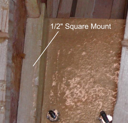
Next, I installed the rear mount. Here you see it underneath the two beams of the ladder mount.
At this point it is not attached to them. The final mounting will be a compression fit between two pieces of plywood, one glued into the structure and one removable as you will see in another picture. This piece is also a laminate of two pieces of 1/8" glued together with slow drying epoxy as were all the engine mount pieces.
.JPG)
Next, here is a picture of the front mounting, so you can see with a little more detail, exactly what I did here. The 1/8" balsa filler pieces up front, near the nose block, are to seal off the engine compartment from the inside of the fuselage, to prevent damage from fuel leakage, and residue.
.JPG) \
\
Here is a closer view of the old original Berkeley balsa filler block, I have kept with the bird down through the years. One thing you will notice is the large hole in it. The plane has always required a lot of nose weight to balance, which I accomplished with a large brass slug I had in it for years. When I got it originally, my friend who put it together in the first place, balanced it with some leftover iron pile plugs. There were all kinds of pieces of junk in the nose of the old girl when I got her. This time, I am going to make it a lot neater. The Anderson engine is heavier than the old Super Cyclone, so that helped some, and the weight of the engine mounting assembly is helping even more. Right now, it balances at about 55% back. I am hollowing out the balsa block as you will see below, and I plan to take lead shot and epoxy and make up a "lead paste" to fill the void in the block and give me some breathing room on the CG. If I find that I need to trim it, a little tail weight will be easy to add. With such a large tail moment that will not require but a tiny bit to do the job, should I need it.
Here is a closer view of the initial rough hole for the weight. Using the Dremel I will hollow out even more as needed. This all will be hidden under the nose planking for a nice tidy fit.
.JPG)
Here is a closer look at the rear mount after I attached it to the fuselage stringers and diagonals. I used once again, some 1/2" square to help it fit tight and secure. At this point I have installed the blind nuts that the top hold down piece will bolt to.
.JPG)
Here is the view from the top showing how the mount is sandwiched between the plywood. Notice that this method will allow an easy adjustment left to right to adjust engine thrust! Quirt ingenious if you ask me. But then I AM a little prejudiced! The bottom piece is glued to the structure and the top piece is bolted down with the mount in between.
.JPG)
Here is how the bottom rear attached to the structure. it is glued to a piece of 1/2" X 1/2" I added on the side of the fuselage, and then the 1/2" brace is glued to the underneath side securely fastening the plywood to the framework.
.JPG)
Below is the nose of the plane. You can see how the mount slips into the nose. It is mounted between the bottom plywood in the lower front, and a piece that is tightly attached above it. This time, neither is removable. The pieces were glued in while the mount was tightly bolted into place. Once the glue was dry, I filled in the void between the top piece and the top of the fuselage with soft 1/8" balsa to seal it up.
.JPG)
As you can see below in the shot I took before sanding out the filler, the the mount is held captive with two bolts. The bolts when tightened, squeeze the plywood holding the mount in place. To prevent slipping, the front mount cross piece is snug against the bolts as you can see. This way, the mount cannot slip forward, but is held in place just where I want it.
.JPG)
Remove the two front bolts, loosen the rear two, and the mount will slide easily out for maintenance or exchange.
.JPG)
Well that is it for now. I plan to start the planking of the nose and bottom of the fuselage right away, in preparation for closing it up.
More to come.....Tommy!